10 hp vfd bldc manufacturers in india
4. Increased temperature rise during motor operation
Under normal working conditions of various household single-phase motors, the surface temperature of the motor shell is generally about 20 ℃ higher than the ambient temperature, and the maximum temperature rise shall not be higher than 70 ℃. If the temperature of the shell surface rises sharply after the motor operates for several minutes, and the tar smell or even smoke is emitted in the motor, it is an overheating fault of the motor.
The main reasons for the motor overheating temperature rise are the quality problems of the motor itself; The motor is overloaded for a long time (the motor load is large due to the failure of the transmission mechanism); Poor heat dissipation condition of motor; Local short circuit of motor winding, etc. The most common one is winding turn to turn short circuit. The casing can be disassembled to check the winding. If the wire package is not burnt out, the stator can be re painted and insulated, and then dried. If the wire package is partially burnt out, only replace the winding wire package.
5. High motor running noise
There are generally two reasons for the high operating noise of the motor. One is the mechanical noise, which is mainly caused by the wear and oil shortage of the motor bearings, resulting in hard friction noise. Add grease after cleaning to reduce noise. When the rotor shaft and bearing are loose or the end cover is loose, the motor will also produce axial movement and noise during rotation. There are also some motors with poor assembly quality, the bearing chambers are not concentric, and the radial clearance of the motor is uneven, which will produce abnormal noise. For this, as long as the outer cover and the rear inner cover are removed, the rotor and stator seat are taken out, and the central shaft of the inner cover is riveted again.
In addition, some shaded pole motors have electromagnetic noise due to loose short-circuit ring or loose iron core, so clamping measures should be taken.
6. Fuselage overheating
1. motor overheating caused by power supply causes fault:
① . the power supply voltage is too high. When the power supply voltage is too high, the back EMF, magnetic flux and magnetic flux density of the motor will increase. As the iron loss is proportional to the square of the magnetic flux density, the iron loss increases, resulting in overheating of the core. The increase of magnetic flux leads to a sharp increase in the excitation current component, resulting in an increase in the copper loss of stator winding 1 and overheating of the winding. Therefore, when the power supply voltage exceeds the rated voltage of the motor, the motor will overheat.
② . the power supply voltage is too low. When the power supply voltage is too low, if the electromagnetic torque of the motor remains unchanged, the magnetic flux will decrease, the rotor current will increase correspondingly, and the load power component in the stator current will increase, resulting in increased copper loss of the winding, resulting in overheating of the stator and rotor windings.

10 hp vfd bldc manufacturers in india
③. Motor connection error. When the delta connection motor is wrongly connected into a star shape, the motor still operates with full load, the current flowing through the stator winding will exceed the rated current, and even cause the motor to stop automatically. If the shutdown time is a little longer and the power supply is not cut off, the winding will not only be seriously overheated, but also be burned out. When a star connected motor is wrongly connected into a triangle, or a motor with several coil groups in series forming one branch is wrongly connected into two branches in parallel, the winding and iron core will overheat, and the winding will be burned in serious cases.
4. motor connection error when one coil, coil group or one phase winding group is connected reversely, it will cause serious imbalance of three-phase current and overheat the winding.
7. Other faults
In the long-term operation of industrial motors, wear faults often occur due to stress: for example, the transmission torque of the reducer connector is large, and the transmission torque is unstable due to the wear of the connecting hole on the flange surface; Bearing wear caused by motor shaft bearing damage; Wear between shaft head and keyway, etc. After the occurrence of such problems, the traditional methods mainly focus on repair welding or machining repair after brush plating, but both of them have certain disadvantages: the thermal stress generated by repair welding at high temperature can not be completely eliminated, which is easy to cause material damage, bending or fracture of components; However, due to the limitation of coating thickness, brush plating is easy to peel off, and the above two methods use metal to repair metal, which cannot change the "hard to hard" coordination relationship, and will still cause re wear under the combined action of various forces. At present, the main method to repair metal with nonmetal is polymer composite. The material has super strong adhesion, excellent compressive strength and other comprehensive properties. The application of polymer composite materials for repair has no effect of repair welding thermal stress, and the repair thickness is not limited. At the same time, the metal materials of the product do not have the concession, which can absorb the impact vibration of the equipment, avoid the possibility of re wear, prolong the service life of equipment components, and save a lot of downtime for the enterprise, Create huge economic value.

10 hp vfd bldc manufacturers in india
MCC motor control center
Definition: motor control center is also called motor control center or motor control center, and its English name is motor control center, or MCC for short. The motor control center manages the power distribution and instrument equipment in a unified way. Various motor control units, feeder connector units, distribution transformers, lighting distribution boards, interlocking relays and metering equipment are installed in an integral enclosure and powered by a common enclosed bus.
In various fields of the national economy, such as electric power, petroleum, chemical industry, metallurgy, mining, papermaking, light industry, automobile, shipbuilding industry, transportation, municipal construction, food and beverage, water treatment, garbage treatment, pharmaceutical, etc., motors are more and more widely used. In order to make the motor run normally and reliably, it is necessary to control and protect the motor of a single motor and the motor of a production line.
Therefore, the level of MCC in motor control center has also developed rapidly. MCC refers to a complete set of motor control and protection equipment connected to AC low-voltage circuit, which is systematically assembled into standardized unit components according to certain specifications. Each component controls a motor of corresponding specifications, and the standard unit components are assembled into a cabinet to realize centralized control of multiple motors.
Working principle: working principle and existing problems of traditional MCC
The traditional MCC is connected to the remote DCS system in the MCC room by control cable and signal cable through hard wiring. The control command of DCS and the feedback information of MCC are transmitted by cable, and each cable is multiple (as shown in Figure 1 below). The traditional MCC control has the following problems:
① A large number of control and signal cables;
② Remote I, O cabinets are required on site;
⑨ Large wiring workload and long installation and commissioning cycle;
④ There are many connection points, so there are many fault points, and the cause of the accident is difficult to find;
⑤ When adding equipment circuits, control and signal cables must be laid again, which is not easy to expand:
⑥ There are few management and diagnostic information for production and operation, and the operation and maintenance of electrical equipment are poor;
⑦ There are a large number of spare parts, which are difficult to unify and occupy a large amount of funds.
Working principle and characteristics of intelligent MCC system
The intelligent MCC system is a new type of electrical automation control system combining information technology, sensing technology and computer data processing technology. Its core component is the motor intelligent protector with communication function. The control instructions of DCS and relevant operation information of motor are carried out through bus communication. Field buses such as lonwbrks, PROFIBUS, etllemet and TCP can be configured with standby communication interfaces as required. Its features are as follows:
① For cabinets without DCS field, usually each communication bus can control up to 100 motor circuits
② Few line contacts, strong anti-interference ability, clear fault causes, easy to find and eliminate;
③ Bus communication mode is adopted, with short installation and commissioning cycle;
④ When adding equipment circuit, if the system allows, it only needs to be set in the software, which is convenient and flexible to expand;
⑤ The operation management information is rich, which can provide detailed equipment maintenance information, achieve preventive maintenance of equipment, and minimize the downtime due to unexpected equipment failure:
⑥ With spare parts management function, the number of spare parts is small, which can reduce the capital occupation.

10 hp vfd bldc manufacturers in india
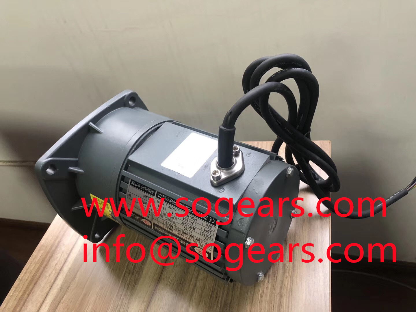
To make the single-phase motor rotate automatically, we can add a starting winding in the stator. The space difference between the starting winding and the main winding is 90 degrees. The starting winding should be connected with a suitable capacitor in series, so that the phase difference between the current and the main winding is approximately 90 degrees, that is, the so-called phase separation principle. In this way, two currents with a time difference of 90 degrees are connected to two windings with a space difference of 90 degrees, which will generate a (two-phase) rotating magnetic field in space. Under the action of this rotating magnetic field, the rotor can start automatically. After starting, when the speed rises to a certain level, the starting winding is disconnected with the help of a centrifugal switch or other automatic control devices installed on the rotor, and only the main winding works during normal operation. Therefore, the starting winding can be made into a short-time working mode. However, in many cases, the starting winding does not open continuously. We call this motor a single-phase motor. To change the direction of this motor, just change the terminals of the auxiliary winding.
In single-phase motor, another method to generate rotating magnetic field is called shaded pole method, also known as single-phase shaded pole motor. The stator of this kind of motor is made of salient pole type, which has two poles and four poles. Each magnetic pole is provided with a small slot at the 1/3--1/4 full pole surface, which divides the magnetic pole into two parts, and a short-circuit copper ring is sleeved on the small part, as if this part of the magnetic pole is covered, so it is called covered pole motor. The single-phase winding is sheathed on the whole magnetic pole, and the coils of each pole are connected in series. When connecting, the polarity generated must be arranged in N, s, N and s in turn. When the stator winding is energized, the main magnetic flux is generated in the magnetic pole. According to Lenz's law, the main magnetic flux passing through the short-circuit copper ring generates an induced current in the copper ring that lags behind 90 degrees in phase. The magnetic flux generated by this current also lags behind the main magnetic flux in phase. Its function is equivalent to that of the starting winding of a capacitive motor, thus generating a rotating magnetic field to make the motor rotate.
Three phase motor
Three phase motor means that when the three-phase stator windings of the motor (each with an electrical angle of 120 degrees difference) are connected with three-phase AC, a rotating magnetic field will be generated. The rotating magnetic field will cut the rotor winding and generate induced current in the rotor winding (the rotor winding is a closed path). The current carrying rotor conductor will generate electromagnetic force under the action of the stator rotating magnetic field, so as to form electromagnetic torque on the motor shaft and drive the motor to rotate, And the rotation direction of the motor is the same as that of the rotating magnetic field.

10 hp vfd bldc manufacturers in india
Performance: ys series three-phase motors are designed and manufactured according to national standards. They are characterized by high efficiency, energy saving, low noise, small vibration, long service life, convenient maintenance, large starting torque, etc. they are class B insulation, IP44 shell protection, ic411 cooling mode, 380V rated voltage and 50Hz rated frequency. They are widely used in food machinery, fans and various mechanical equipment. The executive standard is jb/t1009-2007 totally enclosed motor system with external fan cooling and squirrel cage structure. The utility model has the characteristics of novel design, beautiful appearance, low noise, high efficiency, high torque, good starting performance, compact structure, convenient use and maintenance, etc. The whole machine adopts class F insulation and is designed according to the insulation structure evaluation method of international practice, which greatly improves the safety and reliability of the whole machine. It has reached the advanced level of similar foreign products in the early 1990s. Y2 series motors can be widely used in machine tools, fans, water pumps, compressors, transportation, agriculture, food processing and other mechanical transmission equipment.
Braking mode: there are three electrical braking modes for three-phase induction motor: energy consumption braking, reverse braking and regenerative braking.
(1) During energy consumption braking, cut off the three-phase AC power supply of the motor and send the DC power to the stator winding. At the moment of cutting off the AC power supply, due to the inertia, the motor still rotates in the original direction, and the induced electromotive force and induced current are generated in the rotor conductor. The induced current generates torque, which is opposite to the torque generated by the fixed magnetic field formed after the direct current is fed. Therefore, the motor stops rotating quickly to achieve the purpose of braking. This mode is characterized by stable braking, but DC power supply and high-power motor are required, the cost of DC equipment is large, and the braking force is small at low speed.
(2) Reverse braking is divided into load reverse braking and power reverse braking.
1) Load reverse braking is also called load reverse braking. When the rotor of the motor rotates in the direction opposite to the rotating magnetic field under the action of the heavy object (when the crane uses the motor to lower the heavy object), the electromagnetic torque generated at this time is the braking torque. This torque causes the weight to drop slowly at a steady rate. The characteristics of this kind of braking are: the power supply does not need reverse connection, no special braking equipment is required, and the braking speed can be adjusted, but it is only applicable to wound motor. Its rotor circuit needs to be connected in series with large resistance to make the slip greater than 1.
2) Power reverse connection braking when the motor needs braking, as long as the two-phase power lines are adjusted arbitrarily to make the rotating magnetic field opposite, it can brake quickly. When the motor speed is equal to zero, cut off the power supply immediately. This kind of braking is characterized by fast parking, strong braking force and no need for braking equipment. However, due to the large current and impact force during braking, it is easy to overheat the motor or damage the parts of the transmission part.


