OMRON provides a range of Analog Timers and Digital Timers, as well as Time Switches for 24-hour, weekly, or annual time control.
H3DT-N, H3DT-L, H3DT-A, H3DT-F, H3DT-G, H3DT-H, H3CR-A, H3CR-F, H3Y, H3YN, H3RN, H3DK-M, H3DK-S, H3DK-F, H3DK-G, H3DK-H, H3DS, H3BN-A, H3BN-X, H3Y-C, H5CZ, H3CA, H5CN, H5AN, H7EC-N, H7ET-NV, H7ET-NFV, H7EC-NV, H3BA-N8H, H3CA-8, H5CL-AD, H5S-WA2, H5CX-A, H5CX-AD, H5CX-L8D, H5CX-L8E, H5CX-A11D-N, H5CX-A11-N, H7CX-A4WSD-N
1. Analog Timers
Dial knob setting enables easy operation.
1) H3DT-N / -L
Our Value Design Products Increase the Value of Your Control Panels. Multiple time ranges and operating modes let you cover a wide range of applications.
Control Panels: The Heart of Manufacturing Sites.
Evolution in control panels results in large evolution in production facilities.
And if control panel design, control panel manufacturing processes, and human interaction with them are innovated, control panel manufacturing becomes simpler and takes a leap forward.
OMRON will continue to achieve a control panel evolution and process innovation through many undertakings starting with the shared Value Design for Panel concept for the specifications of products used in control panels.
Our shared Value Design for Panel (herein after referred to as "Value Design") concept for the specifications of products used in control panels will create new value to our customer’s control panels.
Combining multiple products that share the Value Design concept will further increase the value provided to control panels.
Technology and Quality Developed over 80 Years of History.

2) H3DT-A
Our Value Design Products Increase the Value of Your Control Panels. Single Mode Timers with power ON delay operation.
Control Panels: The Heart of Manufacturing Sites.
Evolution in control panels results in large evolution in production facilities.
3) H3DT-F
Our Value Design Products Increase the Value of Your Control Panels. Switch between flicker-OFF or flicker-ON start mode.
4) H3DT-G
Our Value Design Products Increase the Value of Your Control Panels. Set two time ranges between 1 and 120 s with one Timer.
5) H3DT-H
Our Value Design Products Increase the Value of Your Control Panels. Set two time ranges with each Timer, from 0.1 to 12 seconds for the S Series and from 1.0 to 120 seconds for the L Series.
6) H3Y-B
Our Value Design Products Increase the Value of Your Control Panels. Miniature Timer Compatible with the MY Relay.
7) H3CR-A
Multiple Operating Modes and Multiple Time Ranges. DIN 48 x 48-mm Multifunctional Timer.
8) H3CR-F
DIN 48 × 48-mm Twin Timers
9) H3CR-G
DIN 48 × 48-mm Star-delta Timer

2. Digital Timers
Digital Timers provide high-precision operation time settings. Digital switches enable easy preset time settings. Digital displays of elapsed time are also possible.
1) H5CZ
Easy to Use and Easy to Read.
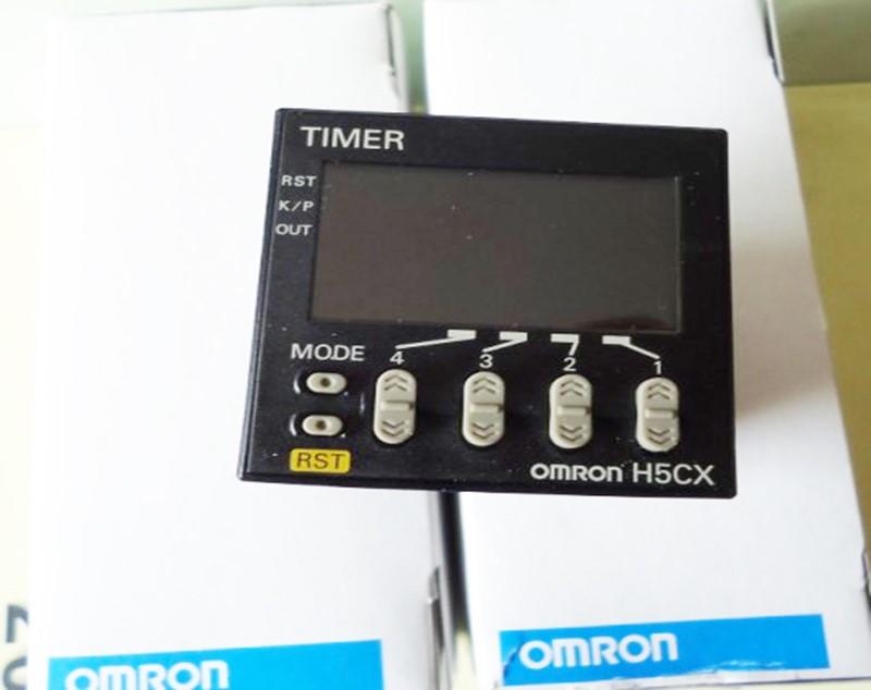
2) H5CX
DIN 48 × 48-mm Multifunction Digital Timer/2-stage Digital Timer
3) H3CA
DIN-sized (48 × 48, 45 × 75 mm) Timer with Digital Setting and LCD Display
4) H5CN
Miniature DIN-sized (48 x 48 mm) Quartz Timer with Abundant Series Versions
5) H5AN
DIN-sized (72 × 72 mm) Quartz Timer with Multiple Functions

3. Delay Relays
OMRON provides the ultra-compact H3FA DIP Timer for PCB mounting.
H3FA
DIP Model Timer for PC Board Use Provides Contact and Solid-state Output
• Four time ranges are selectable.
Models suffixed -[]A[]: 1 s, 10 s, 1 min, 10 min.
Models suffixed -[]B[]: 6 s, 60 s, 6 min, 60 min.
• Timer can be cleaned while mounted on a PC Board with the sealing tape affixed.
• Twenty-four-pin IC socket can be used for mounting the Timer.
• Mountable on a 1-inch pitch rack.
(H 19.5 × W 36.9 × D 17.75 mm)
High reliability in the field of small loads in harsh environments (dust, high humidity, silicon gas, etc.)
The characteristics of OMRON micro switch D2RV are as follows
● The reed switch is used inside the switch.
High contact reliability in the field of small loads.
● The installation pitch of V-type small basic switches is the same.
● The rebound time is less than 1ms, and the service life is long.
Model Voltage specifications Applied voltage Inrush current (peak) time *
H3CR-A / -A8 / -AP AC100 ~ 240V /
DC100 ~ 125V AC264V 780mA 1.8ms
DC137.5V 310mA 3.2ms
AC24 ~ 48V /
DC12 ~ 48V AC26.4V 830mA 2.4ms
DC26.4V 570mA 6.3ms
H3CR-A8E AC100 ~ 240V /
DC100 ~ 125V AC264V 1.76A 0.1ms
DC137.5V 550mA 0.2ms
AC / DC24 ~ 48V AC26.4V 270mA 35ms
DC26.4V 270mA 31ms
H3CR-AS / A8S AC24 ~ 48V /
DC12 ~ 48V AC26.4V 370mA 2.2ms
DC26.4V 250mA 3.2ms
H3CR-F AC100 ~ 240V AC264V 750mA 1ms
AC / DC24V AC26.4V 0.85A 10ms
DC26.4V 0.6A 9.4ms
DC12V DC13.2V 52mA 3.3ms
DC48 ~ 125V DC137.5V 0.5A 9.1ms
H3CR-H
S series
M series
AC100 / 110 / 120V AC132V 1.05A 111ms
AC200 / 220 / 240V AC264V 1.07A 119ms
AC / DC24V AC26.4V 1.26A 133ms
DC26.4V 0.85A 137ms
DC48V DC52.8V 0.73A 112ms
DC100 ~ 125V DC137.5V 0.62A 109ms
AC100 / 110 / 120V AC132V 1.02A 364ms
AC200 / 220 / 240V AC264V 1.03A 323ms
AC / DC24V AC26.4V 1.21A 478ms
DC26.4V 0.87A 560ms
DC48V DC52.8V 0.71A 384ms
DC100 ~ 125V DC137.5V 0.62A 380ms
H3M series AC200 / 220 / 240V AC264V 1.2A 0.5ms
AC100 / 110 / 120V AC132V 620mA 0.4ms
DC110V -- -- --
DC110V -- -- --
DC48V DC52.8V 5A 1ms
DC24V DC26.4V 2.6A 1ms
DC12V DC13.2V 1.3A 1ms
All specifications except H3YN series DC12V -- -- --
DC12V DC13.2V 600mA 1ms
All specifications except H3RN series AC24V -- -- --
AC24V AC26.4V 200mA 60ms
All specifications except H3Y series DC12V -- -- --
DC12V DC13.2V 350mA 0.4ms
H5CX-A / -L AC100 ~ 240V AC264V 5.3A 0.4ms
AC24V / DC12 ~ 24V AC26.4V 6.4A 1.4ms
DC26.4V 4.4A 1.7ms
H5CX-B DC12 ~ 24V DC26.4V 6A 1.2ms
H3CA-A series AC24 ~ 240V /
DC12 ~ 240V AC264V 1.6A 0.6ms
H3CA-8 / -8-306 AC200 / 220 / 240V AC264V 1.5A 0.6ms
AC100 / 110 / 120V AC132V 780mA 5ms
DC24V -- -- --
H3CA-8H / -8H-306 AC200 / 220 / 240V AC264V 1.6A 0.6ms
AC100 / 110 / 120V AC132V 1.5A 5ms
DC24V DC26.4V 1.2A 2ms
H3AM-NS / -NSR AC100 ~ 240V AC264V 2.74A 1.7ms
H3DE AC / DC24 ~ 230V AC253V 4.4A 0.03ms
DC253V 2.68A 0.03ms
DC26.4V 203mA 11ms
H3DE-H AC200 ~ 230V AC200V about 0.8A 130ms
AC100 ~ 120V AC100V about 0.93A 130ms
AC / DC48V AC48V about 0.95A 130ms
DC48V about 0.68A 70ms
AC / DC24V AC24V about 1.25A 140ms

DC24V about 0.89A 40ms
H3DS AC24 ~ 230V /
DC24 ~ 48V AC253V 3A 1ms
DC26.4V 0.5A 4ms
H5BR-B AC100 ~ 240V AC264V 6.7A 1ms
AC24V AC26.4V 8A 2ms
H5CN series AC100 ~ 240V AC264V 500mA 2ms
DC12 ~ 48V DC52.8V 1.2A 3ms
H5AN series AC100 ~ 240V AC264V 16A 1ms
DC100V DC110V 8A 2ms
DC48V DC52.8V 5A 3ms
DC12 ~ 24V DC26.4V 15A 2ms
H3FA-A DC24V DC26.4V 180mA 2ms
DC12V DC13.2V 600mA 2ms
DC6V DC6.6V 660mA 2ms
DC5V DC5.5V 550mA 2ms
H3FA-SA DC24V DC26.2V 180mA 2ms
DC12V DC13.2V 90mA 2ms
DC6V DC6.6V 660mA 2ms
DC5V DC5.5V 550mA 2ms
Precautions for use:
Action time setting
• When setting the operating time, do not turn the knob beyond the scale range. When the time limit needs to be more accurate, please measure the operating time before use and adjust it with the knob.
• The repeating accuracy value of the analog timer operating time is% of the maximum scale time, so even if the setting time is changed, the absolute value of the dispersion will not change. Therefore, please select the time specification and use it as close as possible to the maximum scale.
• If the setting of the analog timer is changed within the set time, the following actions are performed.
Control output
· Please use the control output contact within the rated value range. Please note that if used above the rated value, the contact life will be significantly shortened.
• When switching a small load, check the minimum applicable load stated in each product.
· The life of the contact for control output will vary greatly with the switching conditions. When using, please be sure to confirm on the actual equipment under actual use conditions,
Use within the number of switches with no problem in performance. If you continue to use it in a state of degraded performance, it will eventually cause insulation damage between the circuits and burnout of the relay itself.
· Please avoid the following connections, otherwise it may cause a short circuit between different pole contacts inside the timer.
About the power supply
• Apply power supply voltage quickly through the contacts of switches, relays, etc. If the voltage is applied slowly, the power supply will not reset or the timer time will stop.
• The time when the power is turned on is short. When the inrush current occurs, the timer does not start due to insufficient capacity of the power supply. Use a power supply with sufficient capacity.
For the inrush current value of each model, please refer to page 1490.
· If the power connection is used under AC power, it can be connected to the specified 2 terminals regardless of polarity, but please pay attention to the polarity under DC power.
• In addition, please note that when a voltage different from the rated voltage is applied, or when the wiring is incorrectly connected or the polarity is reversed in the DC specification, it may cause malfunction, abnormal heat generation, and burnout.
· If it is a DC power supply, please set it to the specified ripple rate.
Note. Please refer to the ripple rate of each timer.
· For the application of external pulse voltage between the power terminals, the pulse voltage and current test (JEC-210) established by the Japan Electrical Engineering Institute is used as the standard.
Confirm with a standard waveform of ± (1.2 × 50) μs, but if a pulse voltage exceeding this value occurs, use a surge absorber.
If surge or noise is superimposed on the external power supply, it will cause damage or malfunction of internal components. Therefore, it is recommended that you use components for surge absorption while confirming the circuit waveform.
The surge and noise are different, and the effects of the components are also different. Please check with the actual device.
• When the power is off, do not apply residual voltage or induced voltage.

● Set
When setting with the key switch, do not use claw-shaped or sharp-headed tools. If you use a claw-shaped or sharp-headed tool, the key may be damaged.
● Other
• When carrying out the voltage test, pulse voltage test, insulation resistance measurement, etc. between the electrical circuit and the non-charged metal part with the control panel installed,
In order to prevent the deterioration and damage of the internal circuit of the timer when some parts of the machine inside the control panel and the parts have withstand voltage or poor insulation
① Please disconnect the timer from the circuit. (Unplug the socket from the timer, remove the wiring, etc.) or
②Short all terminals of the terminal section.
· When the device without contact output (such as proximity switch, photoelectric switch or solid state relay, etc.) directly drives the timer,
The timer may malfunction due to the leakage current of the non-contact device. Please confirm it before use.
• Please remove the wiring when replacing the battery. Risk of electric shock if touching high voltage applied parts.
• When switching inductive loads, in order to prevent malfunction or destruction of the timer, install a surge absorbing element.
Regarding the surge absorption element, a diode can be installed in the DC circuit, and a surge absorber can be used in the AC circuit.
A timer is a device that uses a specific principle to measure time. Timers can be used to help you solve these problems. The operation interface is simple and easy to use, and provides basic timing control functions, including: start timing, stop timing, continue timing, the operation interface is simple and easy to reset, adjust the timing.
The types of modern timers include electromagnetic dot timers, spark timers, stick timers, parking timers, reaction timers, amplification timers, and windows timers. Electromagnetic strike timers and spark strike timers are the most common.
Electromagnetic dot timer is a timing instrument using AC power. Its working voltage is 4-6V, the frequency of the power supply is 50Hz, and it strikes every 0.02s. Working principle: When the coil of the electromagnetic timing timer is energized, the coil generates a magnetic field, the vibrating piece in the coil is magnetized, and the vibrating piece moves upward or downward under the action of the magnetic field of the permanent magnet, because the direction of the alternating current changes every cycle Twice, therefore, the magnetic pole of the magnet after the magnet is changed, and the direction of the permanent magnet's force on it must also be changed. When the diaphragm is under the downward force, it is dotted once, when the diaphragm is under the upward force. Dot, so do it once in a cycle of AC, that is, the time interval between every two points is equal to the cycle of AC.
The EDM timer is a timing instrument that uses spark discharge to make small holes in the paper tape to show dots. It uses 220V AC voltage. When the frequency is 50Hz, it hits every 0.02s. When the EDM timer works The resistance to the guided exercise is relatively small, and the test error is smaller than that of the electromagnetic timing timer. Working principle: The spark sparking timer is a timing instrument that uses spark discharge to make the toner print ink dots on the paper tape to show the traces. Connect the 220V power supply to the spark sparking timer, press the pulse output switch, and time The pulse current sent by the device is connected to the discharge needle and toner tray of the positive electrode to the tray shaft connected to the negative electrode, and a spark discharge is generated, so a series of points are punched on the paper tape, and it is discharged once every cycle of the alternating current, so The interval between hitting points of the EDM timer is equal to the period of alternating current.
The input method of OMRON PLC timer is to input BCD code in the timer. If it is 100ms BCD type, if you want to set 3 seconds, you can directly type # 30 in the setting value. # 10 represents the time value of 1 second.
Omron PLC uses programmable memory to store internal instructions for performing logical operations, sequential operations, timing, counting, and arithmetic operations, and can control various types through digital or analog input and output Machinery or production process.
In the input sampling stage, the programmable logic controller sequentially reads all input states and data in a scanning manner and stores them in the corresponding unit in the I / O image area. After the input sampling is completed, it shifts to the user program execution and output refresh phase.
In these two stages, even if the input status and data change, the status and data of the corresponding unit in the I / O image area will not change.
The classification of PLC timer:
1. On-delay timer: On-delay timer is the most common and basic timer in various PLCs. This timer is called SD timer in SIEMENS PLC.
2. Off-delay timer: This timer has no delay effect when the input condition 00000 is ON, and only has a delay effect when the input condition 00000 is OFF. In SIEMENS PLC, it is called SF type timer.
3. Hold-up on-delay timer: This timer generates a latch function when the input condition 00000 is ON, even if the input condition 00000 becomes OFF again, the input condition is still regarded as ON.
When the current value of the timer is equal to the set value, the timer acts. This timer is called SS type timer in SIEMENS PLC. The setting value can be a constant or a channel number. When it is a constant, it must be a BCD code. Add # in front; when it is a channel number, the number in the channel must also be a BCD code.
Omron PLC timer time setting range is 0 ~ 9999.9 seconds.
To set 3 seconds

The internal structure of the mechanical timer principle is mainly composed of three parts:
The first part is the power component, which is a one-way mechanism from the mainspring and the mainspring, so that when it is manually twisted, it can only be tightened, not loose. Tightening the mainspring provides the power for the entire system.
The second part is the release part. A series of gear shifts increase the number of rotation cycles when the mainspring relaxes. At the end of the gear train are escapement wheels, escape pawls and hairsprings to ensure that the speed of the gear train rotates under the drive of the spring. The hairspring has a device for self-adjusting the length of the hairspring, to adjust the frequency of the escapement claw swing, to ensure that the gear rotates at the set speed, will not loosen the tightened spring at once, and is not affected by the tightness of the spring This causes a change in speed.
The third part is the timing trigger device, which makes an electrical signal or mechanical signal after a gear in the gear train turns to a certain angle to stop the power supply or ring the bell.
The three parts work together. When the timer is turned to a certain scale, two things are actually done. One is to tighten the mainspring to provide power to start the timer. The other thing is to set the scale. The trigger position of the trigger mechanism is determined.
Then under the control of the escape wheel, the entire structure slowly releases the power of the mainspring, and the gears at all levels start to rotate at a constant speed until the mechanism is triggered.


