QAMT80L4A
QAMT80L2A
QAMT80L2B
PLD71M4A
PLD80M4A
PLD80M4A
PLD80M4B
PLD80M4B
PLD100L6-4B
PLD-1R2100L6-4A
PLD-1R2100L6-4A
PLD-1R2100L6-4A
BPN180M4B
BPN180L4B
SL112S-4
SL112M4B
SL112S-6-J4
SL112M-6-J4
QASL
QASL71M2B
QASL80M4B
QASL80M4C
QASL90S6/4A
QASL90S6/4A
QASL90S6/4A
QASL100L6/4B
QASL100L4D
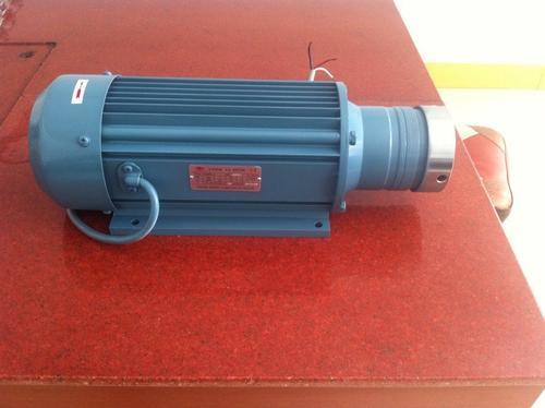
QAMT series grinding head motor is a special motor designed for glass deep processing equipment, to meet the needs of the industry, the shell has good sealing and protection performance, effectively prevent water splashing and dust, to ensure the motor performance. The motor adopts imported high-quality SKF bearing with excellent performance, low noise and long service life, which is suitable for polishing and other glass deep processing machinery. QAMT grinding head motor is the grinding head motor produced by ABB motor, ABB motor quality, buy ABB motor choose sichuan investment, telephone 025-56206366
High speed grinding head motor also known as "high speed grinding head, high speed grinding head motor" because of its excellent performance is widely used in the field of grinding, drilling and milling, etc., is also suitable for high speed grinding bearings such as micro holes and channels.
The grinding head motor
The grinding head motor
At present, the known application of mature fields are: automotive hub, bearing, all kinds of metal material grinding, glass cutting, etc
Grinding head motor features edited
1, high speed, high precision
At present, the maximum speed of domestic grinding head motor can reach 60,000-90,000 / min, and the precision can reach within 5um.
2, stepless frequency conversion speed regulation
Through the inverter can control the desired speed, so greatly improve the efficiency of processing
Grinding head motor general configuration edit
A complete set of grinding head motor, in addition to the motor should also include: fixture, water pump, water tank, water pipe, inverter, cutter, oil injection device and so on above these are indispensable.
At present, grinding is a common process in industrial production. As a common grinding equipment, grinding head motor is widely used. At present, the grinding head motor on the market generally adopts taper positioning for the motor shaft and the grinding wheel shaft. Because spring elasticity and load strength is limited, and the elasticity of the spring after a long time and efforts will subsequently and weaker, the motor and grinding wheel shaft stability is affected by a lot, the motor shaft and grinding wheel spindle taper fit can appear loose due to wear, and it will be more and more big, reduce the service life of the motor and grinding wheel shaft, and the loading and unloading of grinding wheel by pressing handle at the top of the motor shaft head down to the grinding wheel spindle or change, pose a safety hazard, one thousand pressing handle leak on the motor shaft, the motor starts pressing handle will fly out of the hurt person.
Aiming at the above problems existing in the prior art, the purpose of the utility model is to provide a grinding head motor with simple and reasonable structure, convenient and fast operation, stable performance and safe and reliable performance. The grinding head motor, including the motor, and a grinding wheel arranged on the motor are characterized in that the grinding wheel is jacketed on a matching grinding wheel shaft, the grinding wheel shaft and the motor shaft are connected by a wide pitch thread, and a positioning structure is arranged at the connection, and the motor shaft is provided with an anti-rotation structure of the grinding wheel shaft. The grinding head motor is characterized by a limit stop in the middle of the grinding wheel shaft, and the anti-rotation limit structure includes a socket matching inner spline sleeve and outer spline sleeve, the inner spline sleeve is tightly matched and connected to the motor shaft, and the outer end of the outer spline sleeve is inserted into the limit slot of the limit stop. The grinding head motor is characterized in that the positioning structure is a taper bevel arranged with the grinding wheel shaft and the motor shaft. The grinding head motor is characterized in that the grinding wheel is fixed on the grinding wheel shaft with bolts at the outer end of the grinding wheel shaft through a gasket arranged with a baffle. The grinding head motor is characterized in that the inner spline sleeve and the outer spline sleeve have a rotation Angle of 25-30 degrees. The grinding head motor described in [0009] is characterized in that the inner spline sleeve is fixed on the motor shaft through the pin key and the round nut on the outer end. The characteristics of the grinding head motor are that the motor shaft is fitted with a waterproof cover. The characteristics of the grinding head motor lie in that the shim is a flat shim and a stop shim which are successively mounted on the grinding wheel shaft. The grinding head motor described in [0012] is characterized in that the radian of the foreign key of the inner spline sleeve is 30 degrees, and the radian of the groove matched with the outer spline sleeve is 60 degrees. The grinding head motor is characterized in that the inner end of the outer spline sleeve is provided with a bayonet, the bayonet is connected with a spring, and the other end of the spring is pressed against the waterproof cover. Compared with the prior art, the utility model has the following advantages: 1. The motor and the grinding wheel shaft are connected with a wide pitch thread, and the grinding wheel can be loaded and unloaded quickly, which is flexible and convenient, and greatly reduces the replacement time. 2, the grinding wheel shaft adopts taper positioning, the use of thread connection fastening, the work load will not be loose, and the motor shaft and grinding wheel shaft taper parts will never wear, greatly extend the motor and grinding wheel shaft service life. 3. The motor shaft is equipped with an internal and external spline sleeve, which limits the anti-rotation Angle of the grinding wheel shaft through the external spline sleeve, so that only a small amount of the grinding wheel shaft will not fall to the ground and cause the grinding head to break, and will not cause any injury to the human body, so as to ensure safety.
FIG. 1 is the structure diagram of the grinding head motor of the utility model. [0019] FIG. 2 is the structural schematic diagram of the mid-inner spline sleeve of the utility model; FIG. 3 is the structural schematic diagram of the utility model's Chinese and foreign spline sleeve; FIG. 4 and FIG. 5 are structural diagrams of grinding wheel shaft in the utility model. In the figure, 1- motor, la-motor shaft, 2_ oil seal, 3_ waterproof cover, 4_ spring, 5_ pin key, 6_ round nut, 7- grinding wheel, 8- grinding wheel shaft, 8&- limit block.
Specific mode of implementation
The utility model is further described in the following drawings in combination with the specification. As shown in FIG. 1, FIG. 4 and FIG. 5, the grinding head motor includes motor 1, and the grinding wheel shaft 8 connected to the motor shaft la. The grinding wheel 7 is connected to the grinding wheel shaft 8. The grinding wheel shaft 8 is connected with the thread with wide pitch, and is positioned by the taper bevel set on the grinding wheel shaft 8 and the motor shaft la. Grinding wheel spindle central sets limit block 8 a, 8 motor shaft la through key 5 tight fit connection internal spline 14 formed a whole set of spline shaft, spline set within 15 socket in the spline set 14, and internal spline set of 15 sets of 14, spline cooperate with 25 to 30 degrees of rotation Angle, spline set of 15 end plug in limit block 8 a limit groove 8 b. In this embodiment, the radian a of the foreign key of 14 of the inner spline sleeve is 30 degrees, and the radian of the slot 13 of 15 of the outer spline sleeve is 60 degrees, both of which have a rotation Angle of 30 degrees, as shown in FIG. 2 and FIG. 3. [0025] as shown in figure 1, the inner spline sleeve 14 and the outer spline sleeve 15 are fixed on the motor shaft la by the set circular nut 6. The inner end of the outer spline sleeve 15 is provided with bayonet 15a, and the bayonet 15a is connected to spring 4. The other end of the spring 4 is pressed against the waterproof cover 3. The grinding wheel 7 is fixed on the grinding wheel shaft 8 through the flat gasket 9, the stop gasket IO, and the bolt 13 on the outer end of the grinding wheel shaft 8. The product is mainly used the principle of inertia, discharge grinding wheel spindle motor reversing contactor and relay control time when instantaneous reverse spin motor shaft brake completely stopped dead (the size and weight of the grinding wheel to set the rotation time is proportional to the, will be subject to full brake die), because of the external spline set of 15 own inertia effect instantly have 25 to 30 degrees rotation space collision grinding wheel spindle 8, combined with the grinding wheel spindle 8 itself also have inertia, the second force and grinding wheel spindle 8 can easily spin out, because of the external spline set limits the rotation Angle of grinding wheel spindle 8, grinding wheel spindle is only a small amount of exit 8 not drop grinding head rupture or hitting people feet on the ground, At this time, press the outer spline sleeve 15 to the motor 1 into the spring 4, so that the outer spline sleeve 15 to exit the limit slot 8b of the limit block 8a, the grinding wheel shaft 8 can be completely turned out and removed, and then install a new grinding wheel shaft 8, the spring 4 reset, so that the outer end of the outer spline sleeve 15 is inserted into the limit slot 8b of the limit block 8a, complete the whole process of loading and unloading. The motor shaft la and grinding wheel shaft 7 are connected with a wide pitch thread for fastening, taper positioning, convenient loading and unloading, and connection fastening. The outer spline sleeve 15 and the inner spline sleeve 14 cooperate with a spatial rotation Angle of 25-30 degrees. The outer spline sleeve 15 sets a limit to control the rotation Angle of the grinding wheel shaft 7 discharging cutter, so that the grinding wheel shaft 7 will not fall off and will not cause harm to people. Its design structure is reasonable, simple and humanized, stable performance, simple operation, convenient and fast, safe and reliable, is the industry's only one of the best, the safest loading and unloading method.
Claim the grinding head motor, including the motor, and the grinding wheel arranged on the motor, the characteristics of which are that the grinding wheel socket is connected to the matching grinding wheel shaft, the grinding wheel shaft and the motor shaft are connected with a wide pitch thread, and the positioning structure is arranged at the connection, and the motor shaft is provided with the grinding wheel shaft anti-rotation structure.
2. As per claim l, the grinding head motor is characterized by a limit stop in the middle of the grinding wheel shaft. The anti-rotation limit structure includes a socket matching inner spline sleeve and outer spline sleeve. The inner spline sleeve is tightly connected to the motor shaft, and the outer end of the outer spline sleeve is inserted into the limit slot of the limit stop.
3. As for the grinding head motor mentioned in claim l, its feature is that the positioning structure is a taper bevel arranged on the grinding wheel shaft and the motor shaft.
4. As stated in claim l, the grinding head motor is characterized in that the grinding wheel is fixed on the grinding wheel shaft through the gasket set by the baffle and the bolt on the outer end of the grinding wheel shaft is fixed on the grinding wheel shaft.
5. As described in claim 2, the grinding head motor is characterized in that the inner spline sleeve and the outer spline sleeve have a rotation Angle of 25-30 degrees.
6. The grinding head motor mentioned in claim 2 is characterized in that the inner spline sleeve is fixed on the motor shaft through the pin key and the round nut on the outer end.
7. As for the grinding head motor mentioned in claim 2, its feature is that the outer of the motor shaft is fitted with a waterproof cover.
8. As for the grinding head motor mentioned in claim 4, its feature is that the shim is a flat shim and a stop shim which are successively connected to the grinding wheel shaft.
9. As for the grinding head motor mentioned in claim 5, its feature is that the radian of the foreign key of the inner spline sleeve is 30 degrees, and the radian of the slot matched with the outer spline sleeve is 60 degrees.
10. As stated in claim 7, the grinding head motor is characterized by a bayonet on the inner end of the outer spline sleeve , a spring on the bayonet, and the other end of the spring is pressed against the waterproof cover.
Grinding head motor belongs to the technical field of edge grinding machine. It solves the defects of existing technology, such as poor stability and potential safety problems. The grinding head motor, including the motor, and a grinding wheel arranged on the motor are characterized in that the grinding wheel is jacketed on a matching grinding wheel shaft, the grinding wheel shaft and the motor shaft are connected by a wide pitch thread, and a positioning structure is arranged at the connection, and the motor shaft is provided with an anti-rotation structure of the grinding wheel shaft. The utility model has the advantages of reasonable design structure, simple and humanized, convenient and fast operation, stable performance, safe and reliable.
{loadmoduleid 118}


