Transformer is a device that uses the principle of electromagnetic induction to change the AC voltage. The main components are a primary coil, a secondary coil, and an iron core (magnetic core). The main functions are: voltage conversion, current conversion, impedance conversion, isolation, voltage stabilization (magnetic saturation transformer), etc. It can be divided into: power transformers and special transformers (electric furnace transformers, rectifier transformers, power frequency test transformers, voltage regulators, mining transformers, audio transformers, intermediate frequency transformers, high frequency transformers, impact transformers, instrument transformers, and electronic transformers) , Reactors, transformers, etc.). Circuit symbols often use T as the beginning of the number. Example: T01, T201, etc.
A transformer is a static electrical device that transfers electrical energy between two or more circuits through electromagnetic induction. Browse Square D low voltage, medium voltage, and instrument and industrial control transformers – available with products converting utility voltage to building distribution voltage, and converting distribution voltage to application voltage requirements.
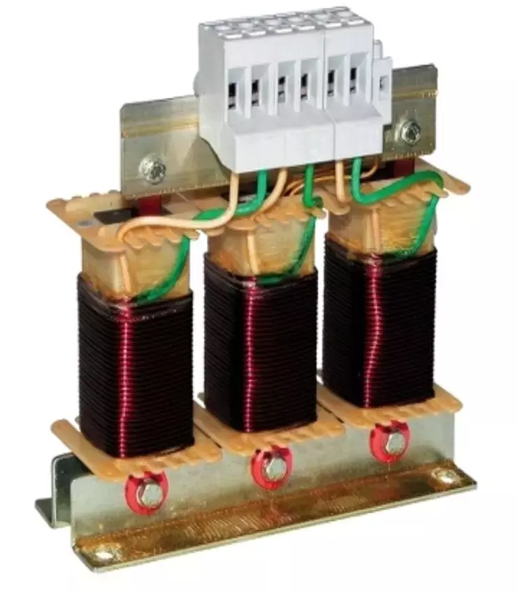
The following is the product model and its introduction:
VW3A4708,VW3A4571,VW3A4568,VW3A4560,VW3A5404,VW3A9612,VW3A7744,VW3A4559,VW3A7752,VW3A7801,VW3A5202,VW3A5307,VW3A4707,VW3A4558,VW3A4570,VW3A9113,VW3A4706,VW3A4712,VW3A5105,VW3A5306,VW3A7708,VW3A7742,VW3A5201,VW3A4407,VW3A9512
Power supply Module,Input 230V.output 24v DC,10.5A,250W ABL 2REM24100H
Controller ,Capacitor ,APFC controller,var plus logic VL6
Transformer ,Reactor ,Detuned Reactor LVRO7250A40T
,Fuse,400v,160A NGT1
Fuse Holder 10x 38 DF 103
Outlet reactor for inverter
product description:
The output AC reactor is used on the load side of the frequency converter, and the motor current flows through these reactors.
The output AC reactor compensates the capacitive charge reversal current of the long cable. If it is a long motor cable, it can limit the dv / dt of the motor terminal.
Performance characteristics:
The core is made of high-quality oriented silicon steel sheet. The core post is divided into uniform small pieces by multiple air gaps. The air gap uses high temperature and high-strength adhesive to tightly bond each small segment of the core post with the upper and lower yoke. The high-quality anti-rust paint spraying process is adopted to solve the rust problem on the surface of the reactor core. Greatly reduced noise and vibration during operation.
Reactors are vacuum-dip lacquered and cured by high-temperature hot-baking. The coil has good insulation performance, high overall mechanical strength, and good moisture resistance.
The coil adopts F and H class insulation system, which greatly improves the reliability of long-term operation.
Low temperature rise, low loss, low cost and high comprehensive utilization rate.
product description:
Reduce motor noise and eddy current loss.
Reduce leakage current caused by input harmonics.
Used for smoothing filtering, reducing transient voltage dv / dt, and prolonging motor life.
Protect the power switching devices inside the inverter.
Technical Parameters:
Rated working voltage: 380V / 50Hz or 660V / 50Hz
Rated working current: 5A to 1600A @ 40 ℃
Electric strength: iron core-winding 3500VAC / 50Hz / 10mA / 10s without flashover
Insulation resistance: 1000VDC insulation resistance value ≥100MV
Reactor noise: less than 65dB
Protection level: IP00
Insulation class: Class F or above
Product performance standards:
IEC289: 1987 reactor
GB10229-88 reactor (eqv IEC289: 1987)
JB9644-1999 reactor for semiconductor electric drive
Output AC reactor 0.5% -1%:
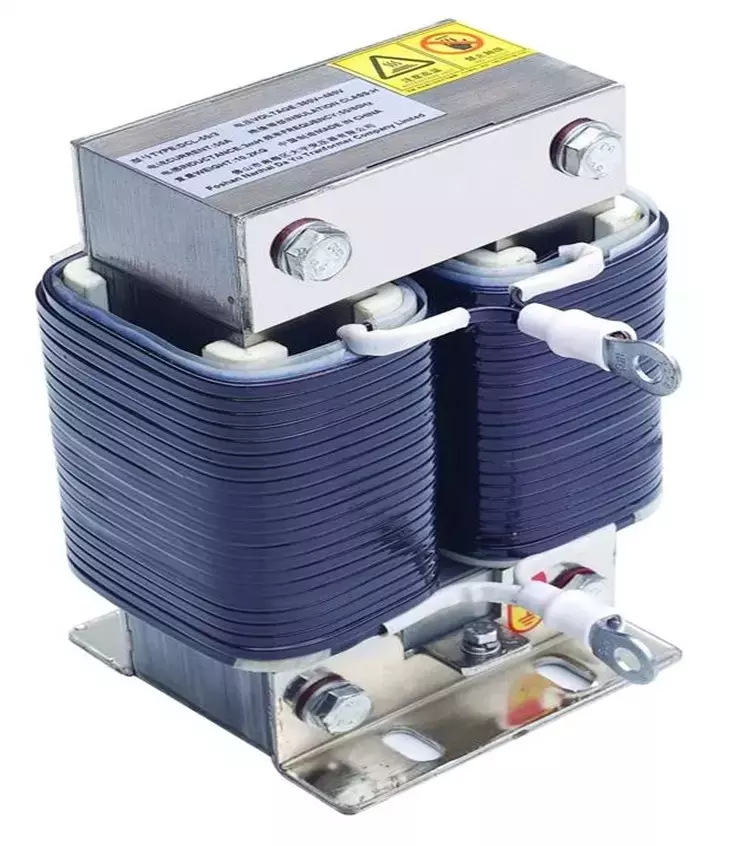
Commonly used reactors in power systems are series reactors and parallel reactors.
The series reactor is mainly used to limit the short-circuit current. There are also series or parallel capacitors in the filter to limit the higher harmonics in the power grid. Reactors in 220kV, 110kV, 35kV, and 10kV power grids are used to absorb the capacitive reactive power of cable lines. The operating voltage can be adjusted by adjusting the number of shunt reactors. EHV shunt reactors have multiple functions to improve the operating conditions of reactive power in power systems, including:
1. Capacitive effect on light no-load or light-load lines to reduce power frequency transient overvoltage;
2. Improve the voltage distribution on long transmission lines;
3. Make the reactive power in the line as balanced as possible at light load to prevent the unreasonable flow of reactive power and also reduce the power loss on the line;
4. When large units and systems are juxtaposed, the power-frequency steady-state voltage on the high-voltage bus is reduced to facilitate the juxtaposition of generators in the same period;
5. Prevent the self-excitation resonance phenomenon that may occur in the long line of the generator;
6. When the neutral point of the reactor is passed through the small reactor grounding device, the small phase reactor can also be used to compensate the phase-to-phase and phase-to-ground capacitance of the line to accelerate the automatic extinguishment of the latent supply current for easy adoption.
The wiring of the reactor is divided into two ways: series and parallel. Series reactors usually function as current limiters, and shunt reactors are often used for reactive power compensation.
1. Half-core dry-type parallel reactor: In the ultra-high-voltage long-distance power transmission system, it is connected to the tertiary coil of the transformer. It is used to compensate the capacitive charging current of the line, limit the system voltage rise and the operating overvoltage, and ensure the reliable operation of the line.
2. Half-core dry series reactor: Installed in the capacitor circuit, starting when the capacitor circuit is put in.
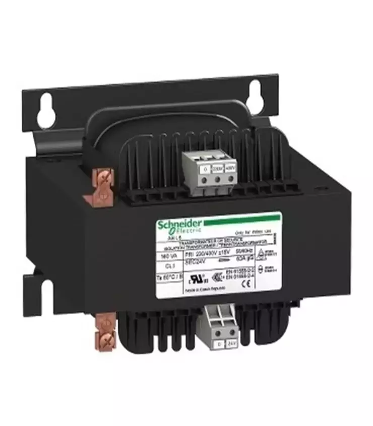
Features:
Line reactor
1. The incoming reactor is three-phase, all are iron core dry type;
2. The iron core is made of high-quality, low-loss imported cold-rolled silicon steel sheet, and the air gap is made of epoxy laminated glass cloth as a gap to ensure that the air gap of the reactor does not change during operation;
3. The coil is wound with H-level enamelled rectangular copper wire, arranged tightly and evenly, with no insulation layer on the surface, and has excellent aesthetics and good heat dissipation performance;
4. The coil and iron core of the incoming reactor are assembled into a whole and then pre-baked → vacuum dip paint → heat-bake and cured. This process uses H-level dipping paint to make the coil and iron core of the reactor firmly combined. , Not only greatly reduces the noise during operation, but also has a very high heat resistance level, which can ensure that the reactor can also run safely and quietly at high temperatures;
5. The non-magnetic material is used for some fasteners of the core of the incoming reactor to reduce the eddy current heating phenomenon during operation;
6. The exposed parts have been treated with anti-corrosion, and the lead-out terminals are tinned copper tube terminals;
7. Compared with similar domestic products, the incoming reactor has the advantages of small size, light weight and beautiful appearance.
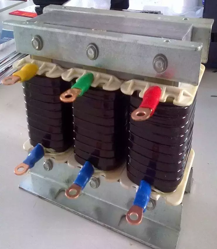
Output reactor
The output reactor is also called a motor reactor, and its role is to limit the capacitive charging current of the motor connection cable and the voltage rise rate of the motor winding to within 54OV / us. The general power is between 4-90KW between the inverter and the motor. When the cable length exceeds 50m, an output reactor should be provided, which is also used to passivate the inverter output voltage (steepness of the switch) and reduce disturbance and impact on components (such as IGBT) in the inverter. The output reactor is mainly used in industrial automation system engineering, especially in the case of using the inverter, to extend the effective transmission distance of the inverter and effectively suppress the instantaneous high voltage generated when the IGBT module of the inverter is switched.
Instructions for using the output reactor: In order to increase the distance between the inverter and the motor, you can appropriately thicken the cable, increase the insulation strength of the cable, and use unshielded cables as much as possible.
Features of output reactor:
1. Suitable for reactive power compensation and harmonic management;
2. The main role of the output reactor is to compensate the influence of the long-distance distributed capacitance and suppress the output harmonic current;
3. Effectively protect the inverter and improve the power factor, which can prevent interference from the power grid and reduce the pollution of the power grid by the harmonic current generated by the rectifier unit.
Input reactor
The role of the input reactor is to limit the voltage drop on the grid side during commutation of the converter; to suppress the decoupling of harmonics and parallel converter groups; to limit the jump in grid voltage or the current impact generated when the grid system is operating. When the ratio of the short-circuit capacity of the power grid to the capacity of the converter inverter is greater than 33: 1, the relative voltage drop of the input reactor is 2% for single quadrant operation and 4% for four quadrant. When the short-circuit voltage of the power grid is greater than 6%, the input reactor is allowed to run. For a 12-pulse rectifier unit, at least one line-side incoming reactor with a relative voltage drop of 2% is required. The input reactor is mainly used in industrial / factory automation control systems and is installed between the inverter, the governor and the power supply input reactor to suppress the surge voltage and current generated by the inverter and the governor. Limitation of higher harmonics and distortion harmonics in systems.
Features of input reactor:
1. Suitable for reactive power compensation and harmonic management;
2. The input reactor is used to limit the current impact caused by the sudden change of the grid voltage and the operating overvoltage; it acts as a filter on the harmonics to suppress the distortion of the grid voltage waveform;
3. Smooth the spike pulses contained in the power supply voltage, and smooth the voltage defects generated during the commutation of the bridge rectifier circuit.
A transformer consists of an iron core (or magnetic core) and a coil. The coil has two or more windings. The winding connected to the power source is called the primary coil, and the remaining windings are called secondary coils. It can transform AC voltage, current and impedance. The simplest core transformer consists of a core made of a soft magnetic material and two coils with different numbers of turns on the core.
The core's role is to strengthen the magnetic coupling between the two coils. In order to reduce the eddy current and hysteresis loss in the iron, the iron core is formed by lamination of painted silicon steel sheets; there is no electrical connection between the two coils, and the coils are wound by insulated copper wires (or aluminum wires). One coil connected to AC power is called the primary coil (or primary coil), and the other coil connected to the electrical appliance is called the secondary coil (or secondary coil). The actual transformer is very complicated. There are unavoidable copper loss (heating of the coil resistance), iron loss (heating of the core), and magnetic leakage (air-closing magnetic induction wire). To simplify the discussion, only the ideal transformer is introduced here. The conditions for an ideal transformer to be established are: ignore the magnetic flux leakage, ignore the resistance of the primary and secondary coils, ignore the core loss, and ignore the no-load current (the current in the primary coil when the secondary coil is open). For example, when the power transformer is running at full load (the output power of the secondary coil) is close to the ideal transformer situation.
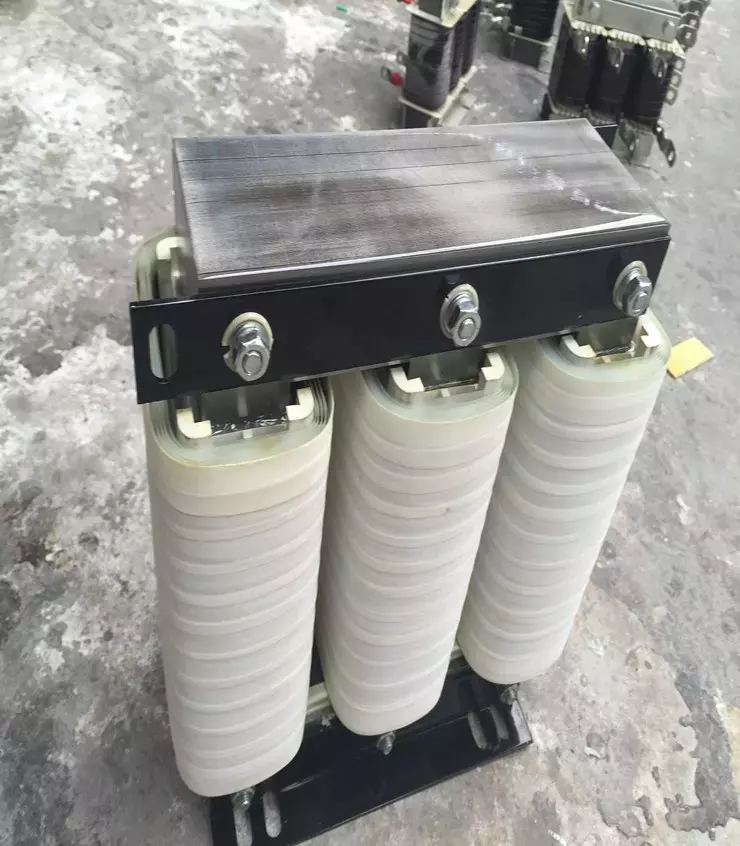
Transformers are stationary electrical appliances made using the principle of electromagnetic induction. When the primary coil of the transformer is connected to an AC power source, an alternating magnetic flux is generated in the core, and the alternating magnetic field is generally expressed by φ. Φ in the primary and secondary coils is the same, φ is also a simple harmonic function, and the table is φ = φmsinωt. According to Faraday's law of electromagnetic induction, the induced electromotive forces in the primary and secondary coils are e1 = -N1dφ / dt and e2 = -N2dφ / dt. In the formula, N1 and N2 are the number of turns of the primary and secondary coils. It can be seen from the figure that U1 = -e1 and U2 = e2 (the physical quantity of the original coil is represented by the subscript 1 and the physical quantity of the secondary coil is represented by the subscript 2). Let k = N1 / N2, called the transformer's ratio. According to the above formula, U1 / U2 = -N1 / N2 = -k, that is, the ratio of the effective value of the transformer primary and secondary coil voltages is equal to the turns ratio and the phase difference between the primary and secondary coil voltages is π.
