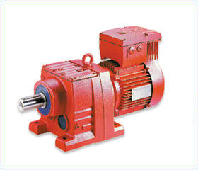
Model of SEW variable frequency all-in-one machine:MOVIMOT
It is a mature and ingenious simple combination of reducer, motor and inverter, with power range from 0.37kw to 4.0kw. Despite the converter integration, the MOVIMOT® requires slightly more space to install than a standard deceleration motor. At the same time, all standard versions and installation locations are available, with or without braking, and the power supply can be 380V to 500V or 200V to 240V.
How to distinguish German SEW motor from frequency conversion motor
1. German SEW motor is designed according to constant frequency and constant voltage, which cannot fully adapt to the requirements of variable frequency speed regulation. The following is the influence of frequency converter on motor
1. Efficiency and temperature rise of German SEW motor
Regardless of the type of inverter, in the operation of the harmonic voltage and current are produced in different degrees, so that the motor in non-sinusoidal voltage, current flow operation. Although the data is introduced, taking the sinusoidal PWM inverter as an example, its low order harmonic is basically zero, and the remaining high order harmonic component about twice the carrier frequency is: 2u+1 (u is the modulation ratio).
The higher harmonics will cause the increase of the copper loss of the motor stator, the copper (aluminum) loss of the rotor, the iron loss and the additional loss. Because the asynchronous motor rotates at a synchronous speed close to the frequency of the fundamental wave, a large rotor loss will occur when the high-order harmonic voltage cuts the rotor guide bar with a large slip. In addition, additional copper consumption due to skin effect should be considered. These losses will make the motor extra heat, efficiency, output power reduction, such as the ordinary three-phase asynchronous motor running in the inverter output of non-sinusoidal power conditions, the temperature rise is generally increased by 10%-20%.
2. German SEW motor strength problem
At present small and medium frequency converter, many is the use of PWM control mode. Its carrier frequency is about several thousand to ten kilohertz, which makes the motor stator winding to bear a very high rate of voltage rise, equivalent to the motor to apply a very steep impact voltage, so that the motor insulation between turns to withstand a relatively severe test. In addition, the rectangular chopper impulse voltage generated by the German SEW motor is superimposed on the operating voltage of the motor, which will pose a threat to the ground insulation of the motor, and the ground insulation will accelerate aging under the repeated impact of high voltage.
3. Noise and vibration of German SEW motor
When the ordinary German SEW motor USES frequency converter to supply power, the vibration and noise caused by electromagnetic, mechanical, ventilation and other factors will become more complex. The time harmonics contained in the variable frequency power supply interfere with the intrinsic spatial harmonics of the electromagnetic part of the motor, forming various electromagnetic excitation forces. When the frequency of the electromagnetic force wave is consistent with or close to the natural vibration frequency of the motor body, the resonance phenomenon will occur, thereby increasing the noise. Due to the wide operating frequency range and the wide rotation speed range of the motor, it is difficult for the frequency of various electromagnetic force waves to avoid the natural vibration frequency of each component of the motor.
4. The adaptability of the motor to frequent starting and braking
Because after power is supplied by Germany the SEW motor, motor can under low frequency and voltage start, in the form of no impact current and frequency converter is available for all kinds of brake way for rapid braking, create conditions for the realization of the frequent starting and braking, and the mechanical system and electromagnetic system of the motor is in circulation under the action of alternating force, brings to the mechanical structure and insulation structure fatigue and accelerated aging problem.
5. Cooling at low speed
Firstly, the impedance of asynchronous German SEW motor is not ideal. When the power frequency is low, the loss caused by the high order harmonic in the power is large. Secondly, when the speed of the ordinary asynchronous motor is reduced, the cooling air volume is proportional to the third square of the speed, resulting in the motor's low-speed cooling condition becomes worse, the temperature rise increases sharply, and it is difficult to achieve constant torque output. Recommended reading: energy-saving motor model
Ii. Characteristics of German SEW motor
1. Electromagnetic design
For German SEW motor, the main performance parameters considered in the redesign are overload capacity, start performance, efficiency and power factor. As the critical slip ratio is inversely proportional to the power supply frequency, the frequency conversion motor can be started directly when the critical slip ratio is close to 1. Therefore, the overload capacity and starting performance do not need too much consideration, but the key problem to be solved is how to improve the adaptability of the motor to the non-sinusoidal power supply. The general way is as follows:
1) reduce the stator and rotor resistance as much as possible.
Reducing the stator resistance can reduce the fundamental copper loss to compensate for the copper loss caused by the higher harmonic
2) to suppress the high order harmonics in the current, the inductance of the motor should be appropriately increased. However, the greater the leakage resistance of rotor groove, the greater the skin effect and the higher the harmonic copper consumption. Therefore, the size of the motor leakage reactance to consider the rationality of impedance matching in the whole speed range.
3) the main magnetic circuit of the frequency conversion motor is generally designed in an unsaturated state. Firstly, considering the high harmonics will deepen the saturation of the magnetic circuit, and secondly, considering the low frequency, the output voltage of the frequency converter should be appropriately increased in order to improve the output torque.
2. Structural design
In the structural design, the influence of non-sinusoidal power supply characteristics on the insulation structure, vibration and noise cooling mode of the inverter motor is mainly considered. Generally, the following problems should be paid attention to:
1) Insulation grade, generally F grade or higher, to strengthen the ground insulation and wire turn insulation strength, in particular, to consider the ability of insulation to withstand impulse voltage.
2)For the vibration and noise problems of the motor, the rigidity of the motor components and the whole should be fully considered, and the natural frequency should be increased to avoid resonance with each force wave. Read more: what are the main parameters of a three-phase asynchronous motor
3) Cooling method: generally, forced ventilation is used for cooling, that is, the main motor cooling fan is driven by an independent motor.
4) Measures to prevent shaft current. For motors with capacity over 160KW, bearing insulation measures shall be adopted. Mainly is easy to produce magnetic circuit asymmetry, also can produce shaft current, when other high frequency components generated by the current combined with the action, the shaft current will be greatly increased, resulting in bearing damage, so generally to take insulation measures.
5) For the constant power variable frequency motor, when the speed exceeds 3000/min, the special high temperature resistant grease should be used to compensate for the temperature rise of the bearing.
SEW is specially equipped with extended ventilation tube and injection tubing for aerator with deceleration motor, which not only prevents the ventilation valve from blocking, but also facilitates maintenance. Scraping and suction machine is a special equipment for sludge concentration tank and sedimentation tank. Technical key: structural design and force calculation of the bridge; The processing of the bridge and the selection and processing of the cross frame and scraper; Determination of driving power; Vertical grid bar layout and pool bottom scraper arrangement; Processing of deceleration mechanism; Overturning protection and automatic, parking and machine PLC automatic control. Main technical parameters: outer edge line speed: 1m/min ~ 2m/min.
Manufacturing method of variable frequency all-in-one machine
The utility model relates to the technical field of a motor, in particular to a heat dissipation structure of a inverter motor body and a controller box.
Background technology:
In the existing technology, frequency conversion control technology is widely used to control the work of the motor in order to improve the operation of the motor. Existing technology in the control box is installed on the motor terminal box, because the motor has cooling fan for the air-filled motor ontology to ensure the reliability of the motor running, and the controller box, no corresponding cooling methods, thus seriously affect the service life of the controller, if the motor controller is also attached to the cooling fan cooling system, such as motor volume miniaturization or so difficult to guarantee the cost of increased significantly.
Technical realization elements:
The purpose of the utility model is to provide a variable frequency all-in-one machine to improve the cooling effect of the controller and reduce the volume of the motor assembly.
In order to achieve the above purpose, adopting the technical scheme for: a kind of frequency conversion machine, including motor body and used for the control PCB layout unit controller box body, in the back end cover of the motor body cover is equipped with the wind hood, controller Settings in the enclosure the box body and the controller box body and cover the wind shield wall formed between airflow pathways, controller box on the motor shaft to the rear end cover up interval layout and arrangement between them has wind deflector, described in central wind deflector opening hole, cooling unit provides the airflow into the end of the wind shield cover and flows through the hole.
Compared with the existing technology, the technical effect of the utility model are as follows: the entire controller box body are in the flow of the air flow path, greatly improving the controller of the box body, cooling effect and cooling unit provides the airflow between cover and wind cover after the flow to the motor frame peripheral cooling fin ontology of motor for cooling, reduce the volume of a frequency conversion motor assembly.
The appended drawings show
FIG. 1 is a schematic diagram of the whole structure of the utility model.
Specific mode of implementation
The utility model is further described in detail in combination with FIG. 1 below.
And a frequency conversion machine includes motor ontology 10 and used for the control PCB layout unit controller box body 20, the ontology of 10 electric motor end cover cover 11 has a wind cover 40, and the controller box body set up in the wind cover 40 and controller box body within 20 and wind cover 40 shield wall flow channel formed between 42, 20 controller box body in the motor shaft to the rear end cover up 11 interval arrangement and arrangement between them have wind deflector 50, described in the central wind deflector 50 open hole is 51, cooling unit provides the airflow from the wind cover 40 cover bottom 41 into and through the hole is 51.
The above scenario, the controller box body set up in the wind cover 40 and controller box body within 20 and wind cover 40 shield wall flow channel formed between 42, only after 20 controller box body and end cover there is a wind deflector arrangement between 50, so that the cooling unit provides the airflow from the wind shield cover bottom into and through the hole is 51, the entire controller box body 20 are in air flow path, and greatly improve the controller 20 the cooling effect of the box body, and the cooling unit provides air flow between the end cover after 11 and wind cover 40 motor frame peripheral ontology 10 on the motor for cooling, reduce the volume of a frequency conversion motor assembly.
The cooling unit comprises a fan impeller 30 between the rear end cover 11 and the windshield plate 50, and a motor rotor 12 is connected with the shaft hole of the fan impeller 30 through the rear end cover 11. Directly through the motor shaft 12 to provide power to the fan impeller 30, so that the fan impeller 30 without additional power mechanism, not only save energy, further reduce the overall volume of the variable frequency motor.
In order to facilitate the connection between the lead wire 13 and the controller, the surface of the windshield board 50 is perpendicular to the axial direction of the motor, and the edge of the windshield board 50 is connected to the windshield wall 42 of the windshield 40. The windshield board 50 is provided with a gap 52. The gap 52 and the inner wall of the windshield 40 form a path for the lead wire 13 of the motor body 10 to pass through.
The controller box body 20 is fixed by connecting block 24 and the hood wall 42 of the windshield 40. The upper two opposite sides of the controller box body 20, the box bottom plate, the box top plate 21 and 22 are perpendicular to the axial direction of the motor. The layout of the controller box 20 is more compact within the windshield 40, which can reduce the length of the windshield 40 in the axial direction of the motor. The layout of the radiator fin 23 can further improve the heat dissipation effect of the controller box 20.
In order to ensure the cooling effect of the motor body 10, the windshield 40 is in the shape of a cylinder and is connected by bolts with a convex block 111 arranged in the 11 circumference of the rear end cover of the motor.


