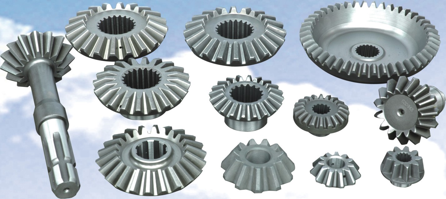
The bevelled gears is used to transmit the movement and power between the two intersecting shafts. In general machinery, the angle of intersection between the two shafts of the bevelled gears is equal to 90° (but it may not be equal to 90°). Similar to cylindrical gears, bevelled gears have indexing cones, addendum cones, tooth root cones and base cones. The cone has a big end and a small end, and the circle corresponding to the big end is called the index circle (its radius is r), the addendum circle, the root circle and the base circle. The movement of a pair of bevelled gears is equivalent to a pair of pitch cones for pure rolling.
The formation of tooth profile:
The formation of the tooth profile of bevelled gears is similar to that of cylindrical gears, except that the base cone is used instead of the base cylinder. The generating surface S is tangent to the generatrix of the base cone. When the generating surface S is purely rolling along the base cone, any straight line OK on the generating surface contacting the generatrix ON of the base cone will form an involute curved surface in space. This curved surface is the tooth profile curved surface of the straight bevelled gears. The trajectory of each point on the line OK is an involute (the involute at the vertex O is a point). Each point on the involute NK is equidistant from the cone O, so the involute must be on a spherical surface centered on the cone O and the radius is OK, that is, NK is a spherical involute.
principle:
The teeth and tooth spaces of bevelled gears are all contracted, that is, they are wide at the big end and narrow at the small end. Although the indexing head has been raised to a root cone angle during processing, the large end of the outer conical surface of the bevelled gears is slightly higher than the small end, and the large end is cut deeper than the small end during milling, and the width of the tooth groove is also larger than the large end. The small end is slightly wider, but this difference cannot meet the requirements. It is necessary to mill out more on both sides of the large end. When milling bevelled gears on a milling machine, after the middle tooth slot is milled out for the first time, the tooth profile of the big end has been obtained, but the slot width dimension does not meet the requirements. Therefore, each tooth slot generally needs to be milled three times to achieve The purpose of milling more on both sides of the big end tooth slot, milling the margin on both sides of the bevelled gears tooth slot is called offset milling. The principle of offset milling is: on the one hand, the workpiece is deflected; on the other hand, the worktable is moved to realign the small end tooth groove with the milling cutter. Using the offset difference between the big end and the small end perpendicular to the feed direction (transverse) when the workpiece is deflected, the milling allowance is gradually increased from the small end to the big end, and the big end is more milled away.
At present, there are many offset milling methods when milling bevelled gears, but due to the inconsistency of the ratio of the pitch to the tooth width (ie R/b), and the difference in parameters such as the pitch angle and the number of teeth, any method cannot be applied to all cones. Gear processing, therefore, can only be selected according to specific conditions and corrected in trial cutting. Often use the combination of rotation and offset for milling.
bevelled gears production process:
1. First, use the hobbing principle to make the machined gear and the imaginary shovel gear repeatedly perform relative hobbing. The tool is a planer with two straight cutting edges, installed on the tool holder, and reciprocating with the tool holder Linear motion.
2. The tool holder is installed on the cradle to form an imaginary shovel gear. The imaginary shovel gear swings from top to bottom and from bottom to top around its own axis line, and the processed gear is mounted on the main shaft of the sub-gear box, and the sub-gear box is moved to make the bevel tip of the processed gear and the imaginary shovel gear bevel tip Coincide, and make the tooth root angle parallel to the surface passed by the tool tip.
3. During gear cutting, the cradle and the gear to be machined respectively make coordinated movements around the axis, that is, as if two bevelled gears mesh, the gear to be machined will be machined under this installation.
4. The axis line and the rotary axis line of the cradle intersect at a point, which is the center of the machine tool. Such mutual movement enables the planer to plan out the correct involute tooth profile.
According to the number and modulus of the workpiece, it is determined to plan the gear with the single tooth method or the double tooth method. For single-piece small-batch production, the single-tooth method is generally used to plan gears.
Spiral bevelled gears have high transmission efficiency, stable transmission ratio, large arc overlap coefficient, high carrying capacity, stable transmission, reliable work, compact structure, energy saving and material saving, space saving, wear resistance, long life and low noise.
The advantages of spiral bevelled gears (compared with straight bevelled gears):
1. Increase the contact ratio, that is, increase the overlap coefficient, reduce the impact, stabilize the transmission, and reduce the noise.
2. The load specific pressure is reduced, the wear is more uniform, the load capacity of the gear is increased correspondingly, and the service life is long.
3. A large transmission ratio can be implemented, and the number of small wheels can be as few as 5 teeth.
4. The tooth surface can be ground to reduce noise, improve the contact area and improve the tooth surface finish. The precision of gear grinding can reach level 5.
Spiral bevelled gears are widely used in printing equipment, automobile differentials, and sluices. They can also be used in locomotives, ships, power plants, steel plants, railway track inspections, etc. Compared with metal gears, plastic gears are economical, have a long wear-resistant life, and are highly functional.
Features of bevelled gears:
Long life, high load carrying capacity
Strong chemical and corrosion resistance
Noise and vibration reduction
Light weight and low cost
Easy to shape, good lubricity
Correction method of tooth thickness during offset milling:
After offset milling on both sides of 2 to 3 teeth with the above method, the large and small ends of the teeth should be inspected. If the actual measured value does not match the value marked on the drawing or calculated, you need to correct the amount of rotation and offset. The principle of correction is:
1. If the size of the small end is accurate and there is margin for the big end, the amount of rotation (or deflection angle) and offset should be increased to increase the difference so that the small end is no longer milled.
2. If the size of the big end is accurate and the tooth thickness of the small end has a margin, the amount of rotation (or deflection angle) should be reduced to reduce the offset more. The small end is also milled away, and the big end is no longer milled.
3. If both the big end and the small end have margins, and the margins are equal, only need to reduce the offset so that both the big end and the small end are milled off.
4. If the size of the small end is accurate and the size of the big end is too small, the amount of rotation (or deflection angle) should be reduced, and the offset should be appropriately reduced so that the small end is no longer milled off, and the big end is cut less than the original some.
5. If the size of the big end is accurate and the size of the small end is too small, the amount of rotation (or deflection angle) should be increased, and the offset should be increased a bit, so that the small end is milled less than the original. If the tooth thickness of the small end is too small when milling the middle groove, you need to replace the milling cutter or make a special milling cutter for processing.
Gear refers to a mechanical element with gears on the rim that continuously meshes to transmit movement and power. The application of gears in transmission appeared very early. At the end of the 19th century, the principle of the generative gear cutting method and the special machine tools and tools that used this principle to cut gear appeared one after another. With the development of production, the smoothness of gear operation was paid attention to.
Structure classification:
Generally, there are gear teeth, tooth grooves, end faces, normal faces, addendum circles, tooth root circles, base circles, and index circles.
Gear teeth
Referred to as a tooth, it is each convex part of the gear used for meshing. These convex parts are generally arranged in a radial pattern. The teeth on the mating gears are in contact with each other, so that the gears can continuously mesh and run.
Cogging
It is the space between two adjacent gear teeth on the gear; the end face is on the cylindrical gear or cylindrical worm, and the plane perpendicular to the axis of the gear or worm.
End face
It is the plane at both ends of the gear.
Dharma
Refers to the plane perpendicular to the tooth line of the gear.
Addendum circle
Refers to the circle where the tip of the tooth is located.
Tooth root circle
Refers to the circle where the bottom of the groove is located.
Base circle
The generating line forming the involute is a purely rolling circle.
Index circle
It is the reference circle for calculating the geometric dimensions of the gear in the end face.
classification:
Gears can be classified according to tooth shape, gear shape, tooth line shape, surface on which the gear teeth are located, and manufacturing method.
The tooth profile of the gear includes tooth profile curve, pressure angle, tooth height and displacement. Involute gears are easier to manufacture, so in modern gears, involute gears account for an absolute majority, while cycloid gears and arc gears are less used.
In terms of pressure angle, gears with small pressure angles have a smaller load-bearing capacity; gears with large pressure angles have higher load-bearing capacity, but the load on the bearing increases under the same transmission torque, so it is only used in special cases. The tooth height of the gear has been standardized, and the standard tooth height is generally adopted. There are many advantages of displacement gears, which have been widely used in various mechanical equipment.
In addition, gears can also be divided into cylindrical gears, bevelled gears, non-circular gears, racks, and worm gears according to their shape; according to the shape of the tooth line, they can be divided into spur gears, helical gears, herringbone gears, and curved gears; according to the gear teeth The surface is divided into external gears and internal gears; according to the manufacturing method, it can be divided into cast gears, cut gears, rolled gears, and sintered gears.
The manufacturing material and heat treatment process of the gear have a great influence on the load-bearing capacity and size and weight of the gear. Before the 1950s, carbon steel was mostly used for gears, alloy steel was used in the 1960s, and case hardened steel was used in the 1970s. According to hardness, tooth surface can be divided into two types: soft tooth surface and hard tooth surface.
Gears with soft tooth surfaces have low load-bearing capacity, but they are easier to manufacture and have good running-in performance. They are mostly used in general machinery with no strict restrictions on transmission size and weight, and small-volume production. Because the small wheel has a heavier burden among the matched gears, in order to make the working life of the large and small gears roughly equal, the hardness of the tooth surface of the small wheel is generally higher than that of the large wheel.
Hardened gears have a high load-bearing capacity. After the gears are cut, they are then quenched, surface quenched or carburized and quenched to increase the hardness. But in the heat treatment, the gear will inevitably be deformed, so after the heat treatment, grinding, grinding or fine cutting must be carried out to eliminate the error caused by the deformation and improve the accuracy of the gear.
material
The commonly used steels for making gears are quenched and tempered steel, quenched steel, carburized and quenched steel and nitrided steel. The strength of cast steel is slightly lower than that of forged steel, and it is often used for larger gears; gray cast iron has poor mechanical properties and can be used in light-load open gear transmissions; ductile iron can partially replace steel to make gears; plastic gears are more commonly used In places where light load and low noise are required, the paired gears generally use steel gears with good thermal conductivity.
In the future, gears are developing in the direction of heavy load, high speed, high precision and high efficiency, and strive to be small in size, light in weight, long life and economical and reliable.
The development of gear theory and manufacturing technology will further study the mechanism of gear tooth damage, which is the basis for establishing a reliable strength calculation method, and the theoretical basis for improving the load-carrying capacity of gears and extending gear life; the development is represented by the arc tooth profile The new tooth profile; research new gear materials and new technology for manufacturing gears; research the elastic deformation of gears, manufacturing and installation errors, and the distribution of temperature fields, and modify the gear teeth to improve the smoothness of gear operation. When increasing the contact area of the gear teeth, so as to improve the bearing capacity of the gear.
Friction, lubrication theory and lubrication technology are the basic work in gear research. Research on elastohydrodynamic lubrication theory, popularize the use of synthetic lubricating oil and appropriately add extreme pressure additives to the oil, which can not only improve the bearing capacity of the tooth surface, but also It can also improve transmission efficiency.

The difference with hypoid bevelled gears:
Spiral bevelled gears and hypoid bevelled gears are the main transmission modes used in automobile final reducers. What is the difference between them?
The main and driven gear axes intersect at a point, and the angle of intersection can be arbitrary, but in most automobile drive axles, the main reducer gear pair adopts a 90° vertical arrangement. Due to the overlap of the end faces of the gear teeth, at least two or more pairs of gear teeth mesh at the same time. Therefore, the spiral bevelled gears can bear a relatively large load. In addition, the gear teeth are not meshed at the same time over the full tooth length, but gradually meshed One end is continuously turned to the other end, so that it works smoothly, and even at high speed, the noise and vibration are very small.
The axes of the driven gears do not intersect but intersect in space, and the intersecting angle of the space also adopts a 90° angle different plane vertical method. The driving gear shaft has an upward or downward offset relative to the driven gear shaft (referred to as upper or lower offset accordingly). When the offset is large to a certain extent, one gear shaft can pass by the other gear shaft. In this way, compact bearings can be arranged on both sides of each gear, which is beneficial for enhancing the support rigidity and ensuring the correct meshing of the gear teeth, thereby increasing the gear life. It is suitable for through-type drive axles.
Unlike the spiral bevelled gears, where the main and driven gears have the same helix angle because the axes of the gear pair intersect, the axis offset of the hypoid gear pair makes the helix angle of the driving gear greater than the helix angle of the driven gear. Therefore, although the normal modulus of the hypoid bevelled gears pair is equal, the end face modulus is not equal (the end face modulus of the driving gear is greater than that of the driven gear). This makes the driving gear of the quasi-double-sided bevelled gears transmission have a larger diameter and better strength and rigidity than the driving gear of the corresponding spiral bevelled gears transmission. In addition, due to the large diameter and helix angle of the driving gear of the hypoid bevelled gears transmission, the contact stress on the tooth surface is reduced and the service life is increased.
However, when the transmission is relatively small, the driving gear of the quasi-double-sided bevelled gears transmission is too large compared to the driving gear of the spiral bevelled gears. At this time, it is more reasonable to choose the spiral bevelled gears.

Spiral bevelled gears, namely spiral bevelled gears, are often used for movement and power transmission between two intersecting shafts. The teeth of the bevelled gears are distributed on the surface of a cone, and the tooth profile gradually decreases from the large end to the small end.
Introduction:
The tooth profile of spiral bevelled gears is arc-shaped, and they are generally cone-shaped, like an umbrella shape, hence the name spiral bevelled gears.
Spiral bevelled gears is a transmission part that can be transmitted smoothly and with low noise according to a stable transmission ratio. It has different names in different regions. It is also called spiral bevelled gears, spiral bevelled gears, spiral bevelled gears, arc bevelled gears, Spiral bevelled gears, etc.
Features:
Spiral bevelled gears have high transmission efficiency, stable transmission ratio, large arc overlap coefficient, high carrying capacity, stable and smooth transmission, reliable work, compact structure, energy saving and material saving, space saving, wear resistance, long life and low noise.
Among various mechanical transmissions, the transmission efficiency of spiral bevelled gears is the highest, which has great economic benefits for various types of transmissions, especially high-power transmissions. The transmission pair required to transmit the same torque is the least space-saving. The space required for chain transmission is small; the transmission ratio of spiral bevelled gears is permanently stable, and stable transmission ratio is often the basic requirement for transmission performance in the transmission of various mechanical equipment; spiral bevelled gears work reliably and have a long life.
application:
Spiral bevelled gears are widely used in domestic and foreign oilfield petrochemical machinery, various machine tools, various machining equipment, engineering machinery, metallurgical equipment, steel rolling machinery, mining machinery, coal mining machinery, textile machinery, shipbuilding machinery, shipbuilding industry, aerospace, forklift , Elevators, reducers, aircraft manufacturing and many other industries. Spiral bevelled gears are used in a variety of mechanical equipment, showing their excellent performance, and are popular among aerospace equipment manufacturers, shipyards, engineering machinery plants, metallurgical equipment plants, steel rolling spare parts plants, steel rolling machinery plants, steel rolling mills, Metallurgical machinery plant, mining machinery plant, coal mining machinery plant, oil field petrochemical machinery plant, textile machinery plant, machine tool plant, equipment company, elevator company, aircraft manufacturing plant, reducer plant, coal mining machinery plant, light industry machinery plant, steel rolling mill , Steel rolling equipment factory, metallurgical equipment factory and other customers.
Please feel free to contact us and here following is our contacts. We will reply you as soon as possible! Mobile:+86-18563806647 Whatsapp/Wechat: 8618563806647 E-mail: 

Yantai Bonway Manufacturer Co.ltd ANo.160 Changjiang Road, Yantai, Shandong, China(264006) T+86 535 6330966 W+86 185 63806647


