Servo motor is respected and talked about by current engineers, it is almost unimaginable to mention motion control without talking about servo motor, engineers are obsessed with servo motor closed-loop control, intoxicated with the advantages of high response and high speed and high precision, really "three high".However, as the saying goes, the servo motor has the following inevitable defects:
1. Unable to rest: with closed loop control, servo motor itself structure and the characteristics of the decision, servo motor can't absolute rest when to stop, in a small load disturbance or servo motor parameter debugging good cases, the servo motor is always fluctuates between plus or minus 1 pulse (about the encoder position servo drive can be observed values, which fluctuated between plus or minus 1).In the case of image processing this is a factor affecting accuracy.
2. Overshoot: when changing from high speed to low speed or stationary, it is inevitable to overshoot for a certain distance and then correct back.When the controller sends a pulse to the servo motor, the servo motor usually goes not one pulse, but three pulses, and then two pulses back.This is fatal for situations where one pulse is required to move one pulse at a time, and overshooting is absolutely not allowed.
3. Debugging is complicated: the servo driver often contains hundreds of parameters and hundreds of pages of instructions, which really makes the novice afraid;Changing a brand of servo motor can also be a real headache for the veteran.This also brings a lot of work for after-sales service and maintenance.
4. Low speed peristalsis: peristalsis or creeping occurs when the servo motor is running at low speed.
The closed-loop stepper motor perfectly solves the above problems.
First of all, the closed-loop stepper motor is absolutely stationary at rest because the motor itself is a stepper motor.
Secondly, because the closed-loop stepping motor combines the characteristics of stepping motor and servo control mode, it will not overshoot (because the characteristics of stepping motor is not overshoot).
Third, debugging and use is very simple, only need to adjust the position of the driver's 3 potentiometers, not only equipment manufacturers can use, but also equipment users can use, the user requirements are very low.
This article, is to avoid the point that the closed-loop stepper motor is good, to bury the servo motor, not objective.
1. Unable to stay still, the stepper motor is relatively better because of the internal lattice structure locking, and relatively calorific.Servo motor internal by the current and encoder to position lock, is in a back and forth pulse jumping characteristics, actual use can be appropriate to adjust the motor rigidity to improve its locking torque and performance.
2. Overshoot. The closed-loop stepping motor is a system that exists to solve overshoot and missing step.In my actual use, if the stop speed is short, overshoot will often occur. However, I don't care much about this problem because the environment is not rigorous, because the closed loop will eventually return to its own position. If overshoot is to be solved, I think it still needs programmers to adjust the speed rise and fall curve and time.
3. Debugging is complicated, and you need to learn it every day. This debugging is still based on the engineer having designed the driver parameters.
4. Low speed peristaltic, adjust the servo drive gear plate mechanically according to the specific situation to reduce peristaltic.
Cost, also realizes the function of servo motor price indeed than with power closed loop stepper motor, there are advantages in shangbu ratio of motor, but the actual is: a penny a points goods, a lot of closed loop stepper motor, motor, though ready, but the drive and the corresponding function is more humble, the pursuit of the details still need to use servo system.
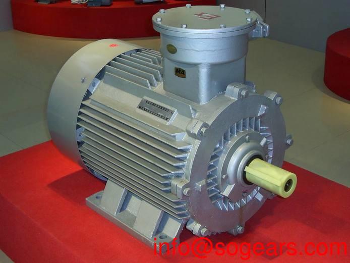
Ac asynchronous motor is the leading ac voltage running motor, widely used in electric fans, refrigerators, washing machines, air conditioners, hair dryers, vacuum cleaners, range hoods, dishwashers, electric sewing machines, food processors and other household appliances and various electric tools, small electromechanical equipment.
Ac induction motors are divided into induction motors and ac commutator motors.Induction motor is divided into single-phase asynchronous motor, ac and dc dual-use motor and repulsion motor.
The speed of the motor (rotor speed) is less than the speed of the rotating magnetic field.It's basically the same thing as an induction motor.S = (ns - n)/ns.S is slip,
Ns is magnetic field speed, n is rotor speed.
The structure of three-phase asynchronous motor is similar to that of single-phase asynchronous motor. Its stator core slot is embedded with three-phase windings (with single-layer chain, single-layer concentric and single-layer crossover).When stator winding is connected to three-phase ac power supply, the rotating magnetic field generated by winding current generates induction current in the conductor of the rotor. Under the interaction of induction current and air gap rotating magnetic field, the rotor generates electromagnetic rotating cabinet (namely asynchronous rotating cabinet), making the motor rotate.
Basic principle:
1. When the three-phase asynchronous motor is connected to the three-phase ac power supply, the three-phase stator winding flows through the three-phase symmetrical current to generate the three-phase magnetomotive force (stator rotating magnetomotive force) and generates the rotating magnetic field.
2. The rotating magnetic field has relative cutting motion with the rotor conductor. According to the principle of electromagnetic induction, the rotor conductor generates induced electromotive force and induced current.
3. According to the law of electromagnetic force, the current-carrying rotor conductor is affected by electromagnetic force in the magnetic field, forming an electromagnetic torque, which drives the rotor to rotate. When the motor shaft is loaded mechanically, it outputs the mechanical energy outwardly.
Induction motor is an ac motor, its load speed and the connected network frequency ratio is not a constant relationship.It also varies with the size of the load.The larger the load torque, the lower the rotor speed.Induction motor including induction motor, doubly-fed induction motor and ac commutator motor.Induction motor is the most widely used, not causing misunderstanding or confusion in the case, generally known as induction motor induction motor.
The stator winding of ordinary induction motor is connected to ac power grid, and the rotor winding does not need to be connected with other power sources.Therefore, it has the advantages of simple structure, convenient manufacturing, use and maintenance, reliable operation, lower quality and lower cost.Asynchronous motor has higher operating efficiency and better working characteristics, from no load to full load range near constant speed operation, can meet most industrial and agricultural production machinery transmission requirements.Induction motor is also easy to derive into various types of protection, to adapt to the needs of different environmental conditions.When the asynchronous motor is running, the reactive excitation power must be absorbed from the power grid, so that the power factor of the power grid becomes bad.Therefore, the drive ball mill, compressor and other high power, low speed mechanical equipment, often use synchronous motor.Because the speed of the induction motor and its rotating magnetic field speed has a certain slip relationship, its speed regulation performance is poor (except ac commutator motor).It is more economical and convenient to adopt dc motor for transportation machinery, rolling mill, large machine tools, printing and dyeing machinery and papermaking machinery that require wide and smooth speed regulation range.However, with the development of high-power electronic devices and ac speed regulating system, the speed regulating performance and economy of wide speed regulating induction motor have been comparable to that of dc motor.
The stator consists of a frame and an iron core with winding.The core is superposed by the punching groove of silicon steel sheet, and the groove is embedded with two sets of main windings (also known as running windings) and auxiliary windings (also known as starting windings) which are separated from each other by 90° electrical Angle.The main winding is connected to the ac power supply, and the auxiliary winding is connected to the centrifugal switch S or the starting capacitor and operating capacitor in series, and then connected to the power supply.
The rotor is a cage cast aluminum rotor, which is used to cast the iron core into the slot of the iron core after lamination, and cast the end ring together to short-circuit the rotor guide bar into the squirrel cage type.
Single-phase asynchronous motor is divided into single-phase resistor starting asynchronous motor, single-phase capacitor starting asynchronous motor, single-phase capacitor running asynchronous motor and single-phase double-value capacitor asynchronous motor.
Cage type chute cast aluminum rotor is usually used.According to the different stator configuration, it can be divided into salient pole type hood motor and implicit pole hood motor.
The stator core of the salient pole hood motor is a square, rectangular or circular magnetic field frame with protruding magnetic poles. On each pole there is one or more auxiliary short-circuit copper rings, namely hood windings.The concentrated winding on the salient magnetic pole is the main winding.
Non-salient pole type cover pole motor stator core is the same as the common core of single-phase motor, the stator winding adopts the distributed winding, the main distribution in stator slot winding, shaded pole winding don't short circuit copper ring, but with the coarser the enameled wire wound as distributed winding (series after short circuit) embedded in the stator slot (about two-thirds of the total number of slots), a support group.The main winding and the hood winding are spaced at a certain Angle from each other.
When the main windings of the cover pole motor are energized, the cover pole windings will also generate induction current, so that the stator magnetic pole covered by the cover pole windings will rotate the part of the flux and the uncovered part towards the direction of the cover pole windings.
The stator of single-phase series motor is composed of salient pole core and excitation winding, and the rotor is composed of hidden pole core, armature winding, commutator and rotating shaft.A series circuit is formed between the excitation winding and armature winding through the brush and commutator.
Single-phase series motor belongs to ac and dc dual-purpose motor, which can work with ac power supply and dc power supply.
Synchronous motor and induction motor are common ac motors.The characteristics are as follows: in steady-state operation, there is a constant relationship between rotor speed and power grid frequency n=ns=60f/p, and ns becomes synchronous speed.If the frequency of the power network is constant, the speed of the synchronous motor is constant and independent of the load.Synchronous motor is divided into synchronous generator and synchronous motor.Synchronous motor is the main alternator in modern power plant.

The establishment of the main magnetic field: the excitation winding is connected with the dc excitation current, and the excitation magnetic field with polarity is established, that is, the main magnetic field is established.
Current-carrying conductor: three-phase symmetrical armature winding ACTS as the power winding and becomes the carrier of induced potential or induced current.
Cutting motion: the prime mover drives the rotor to rotate (input the mechanical energy to the motor), and the polarized excitation magnetic field rotates with the shaft and cuts the stator windings successively (equivalent to the conductor reverse cutting excitation magnetic field of the winding).
The generation of alternating potential: due to the relative cutting motion between the armature winding and the main magnetic field, the armature winding will be induced to the size and direction of the three-phase symmetric alternating potential which changes periodically.Ac power supply can be provided through the lead wire.
Alternation and symmetry: alternating polarity of induced potential due to rotating magnetic field;Because of the symmetry of armature winding, the three-phase symmetry of induction potential is guaranteed.
Ac synchronous motor is a kind of constant speed drive motor, its rotor speed and power frequency maintain a constant proportional relationship, is widely used in electronic instruments, modern office equipment, textile machinery and so on.
Permanent magnet synchronous motor
Permanent magnet synchronous motor belongs to asynchronous start permanent magnet synchronous motor, whose magnetic field system is composed of one or more permanent magnets, usually in the cage rotor made of cast aluminum or copper strip welding, according to the required number of poles mounted with the magnetic poles of permanent magnets.The stator structure is similar to that of an asynchronous motor.
When the stator winding is connected to the power supply, motor with principle of asynchronous motor starting regulated, rev to synchronous speed, generated by the permanent magnet rotor magnetic field and stator magnetic field of synchronous electromagnetic torque, the electromagnetic torque generated by the permanent magnet rotor magnetic field and the magnetic resistance torque of the stator magnetic field to produce synthesis) will pull in synchronous rotor, into synchronous motor running.
Reluctance synchronous motor is also known as reactive synchronous motor. It is a synchronous motor that generates reluctance torque due to the difference in the magnetoresistance between the quadrator and the straight axis of the rotor. Its stator structure is similar to that of the asynchronous motor, but the rotor structure is different.
Reluctance synchronous motor
With the evolution of cage induction motor, in order to make the electric function produce asynchronous start torque, the rotor is also equipped with cage cast aluminum wound.The rotor is provided with a reaction slot corresponding to the number of stator poles (only the salient pole part, no excitation winding and permanent magnet), which is used to generate reluctance synchronous torque.According to the different structures of reaction slots on the rotor, it can be divided into internal reaction type rotor, external reaction type rotor and external reaction type rotor.The internal groove of the internal reaction rotor blocks the magnetic flux in the direction of the cross axis and increases the magnetic resistance.The internal and external reaction rotor combined with the above two types of rotor structure characteristics, the direct shaft and the quadrature shaft difference, so that the motor force energy is greater.Reluctance synchronous motors can also be divided into single-phase capacitor running type, single-phase capacitor starting type, single-phase double-value capacitor type and other types.
Hysteresis synchronous motor is a kind of hysteresis motor which USES hysteresis materials to generate hysteresis torque.It is divided into internal rotor type hysteresis synchronous motor, external rotor type hysteresis synchronous motor and single-phase bonnet type hysteresis synchronous motor.
The rotor structure of the internal rotor hysteresis synchronous motor is non-salient pole type, with a smooth cylindrical appearance. There are no windings on the rotor, but there is a ring effective layer made of hysteresis material on the outer circle of the core.
After the stator winding is connected to the power supply, the generated rotating magnetic field causes the hysteresis rotor to produce an asynchronous torque and start rotating, and then pull itself into synchronous operation.When the motor is running asynchronously, the stator rotating magnetic field magnetizes the rotor repeatedly at the slip frequency.In synchronous operation, the hysteresis material on the rotor is magnetized and a permanent magnet magnetic pole appears, thus generating synchronous torque.The soft starter adopts three parallel parallel thyristors as the voltage regulator, which is connected to the power supply and the stator of the motor.Such circuit is like three - phase full - control bridge rectifier circuit.When starting the motor with a soft starter, the output voltage of the thyristor increases gradually and the motor accelerates gradually until the thyristor is fully switched on. The motor works on the mechanical characteristics of the rated voltage to realize smooth start, reduce the starting current and avoid starting overcurrent trip.When the motor reaches rated revolution, the starting process is over, and the soft starter will automatically replace the completed thyristor with bypass contactor to provide rated voltage for the normal operation of the motor, so as to reduce the heat loss of the thyristor, extend the service life of the soft starter, improve its working efficiency and avoid harmonic pollution in the power grid.The soft starter also provides a soft stop function. In contrast to the soft start process, the voltage gradually decreases and the revolution gradually drops to zero to avoid the torque shock caused by free stop.
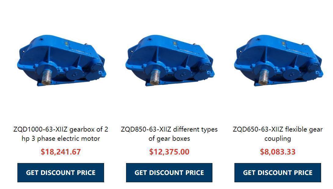
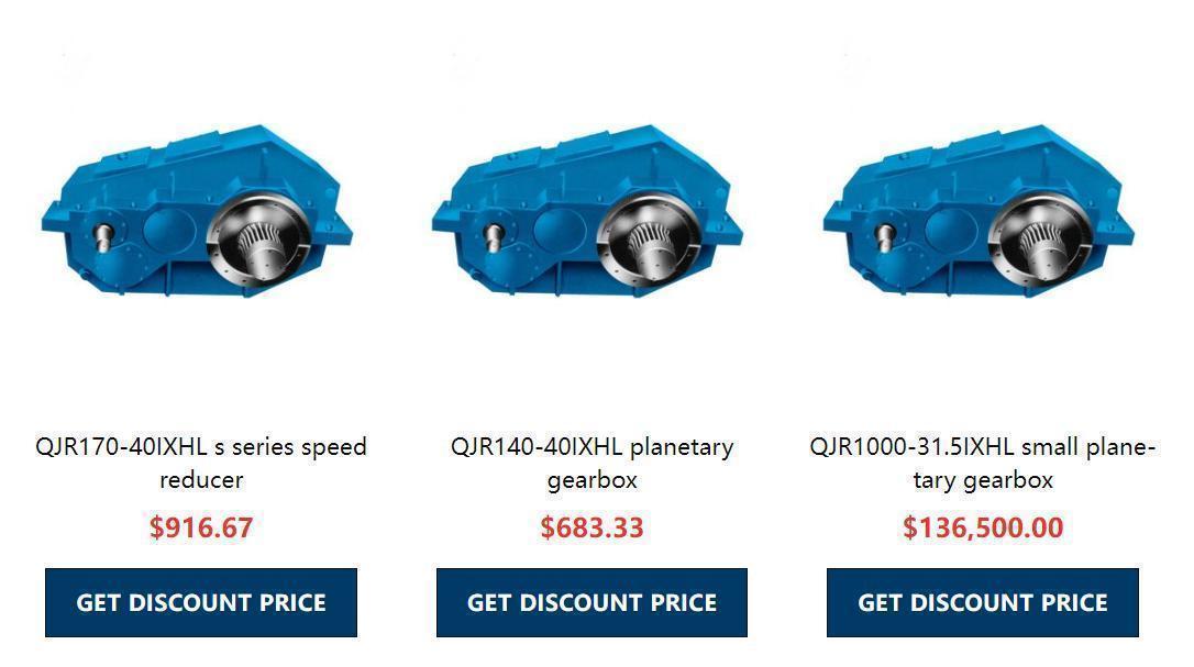
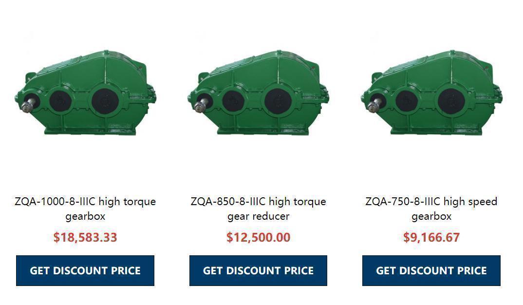
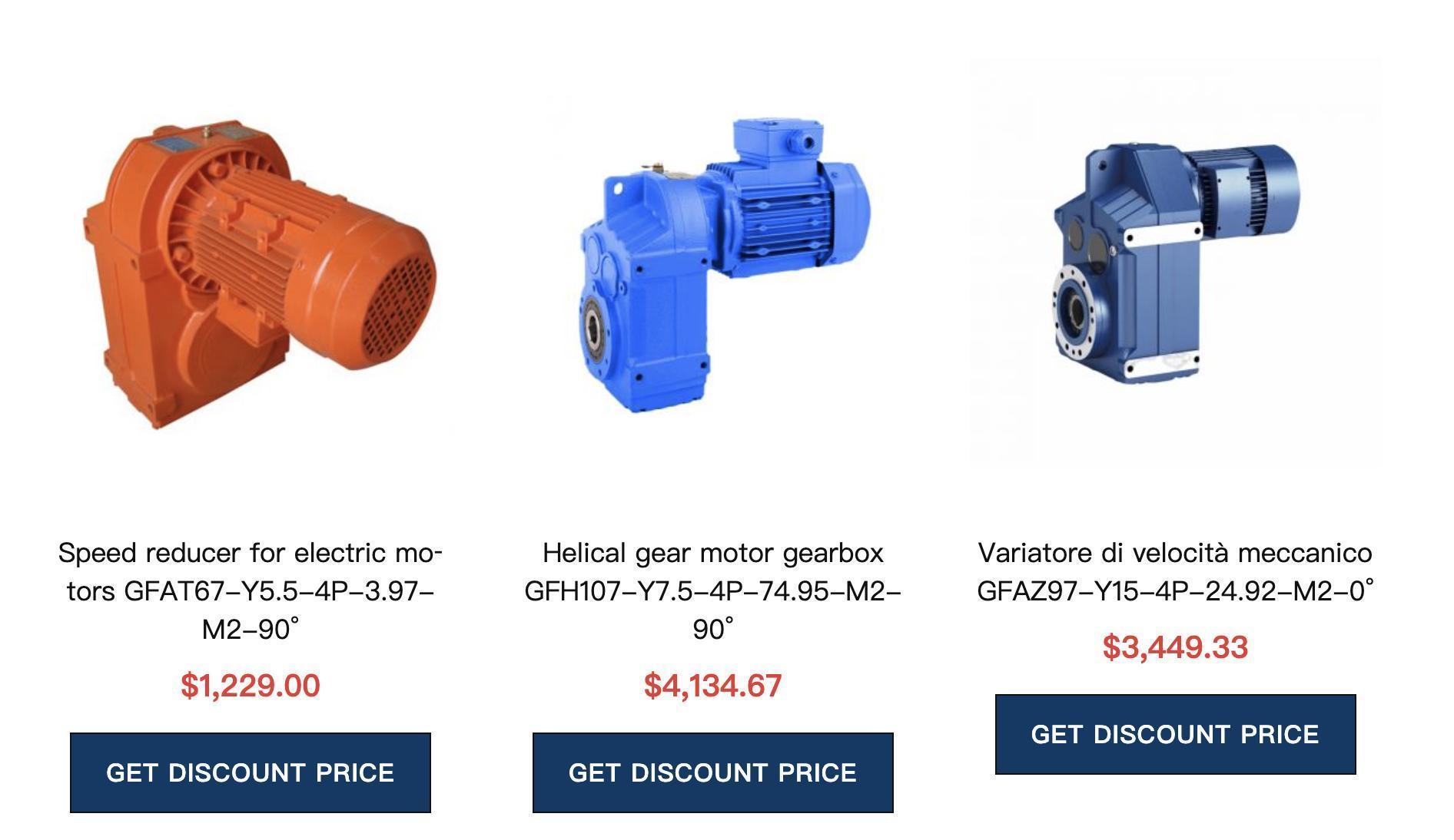
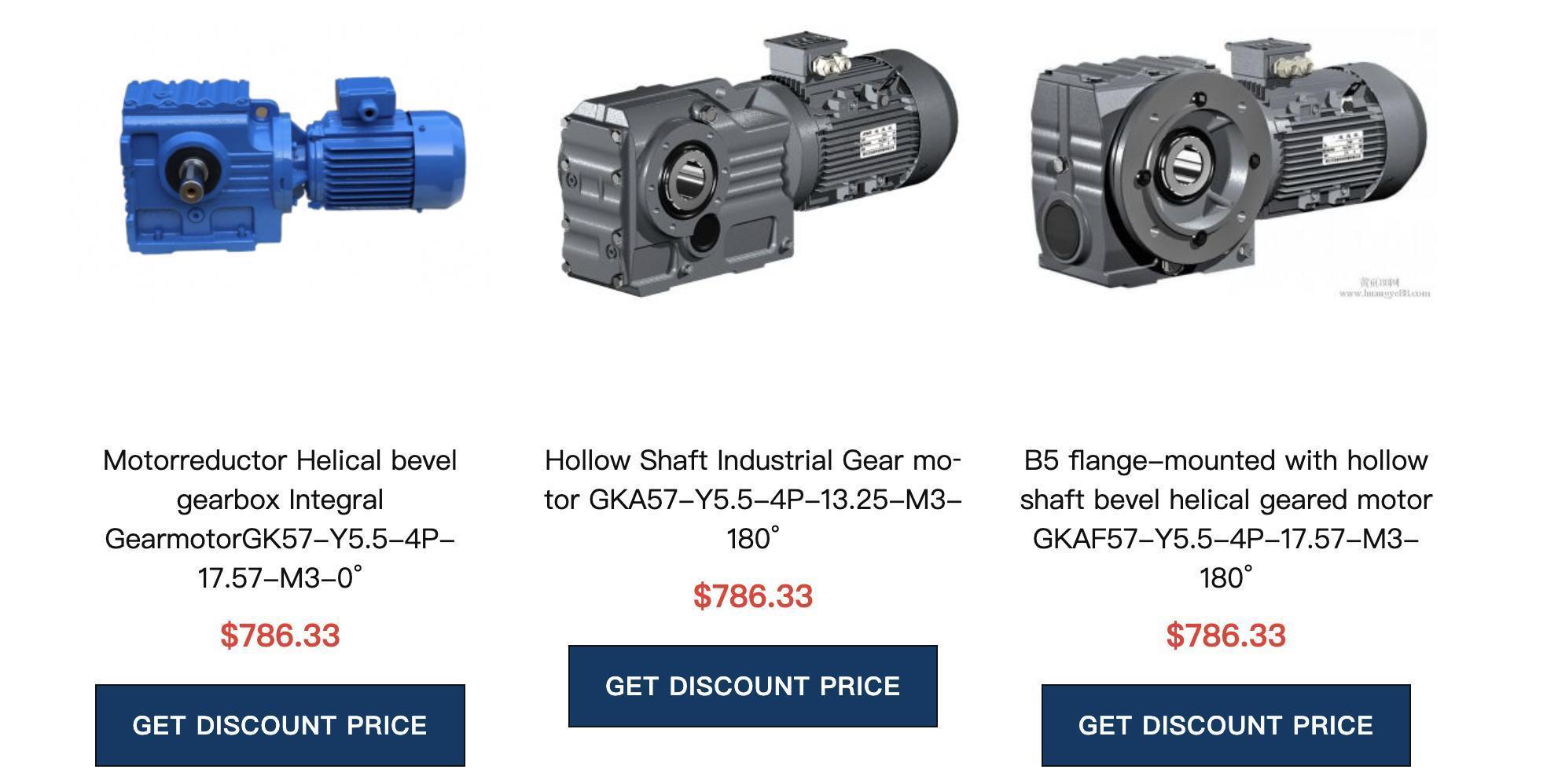
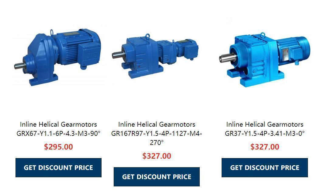
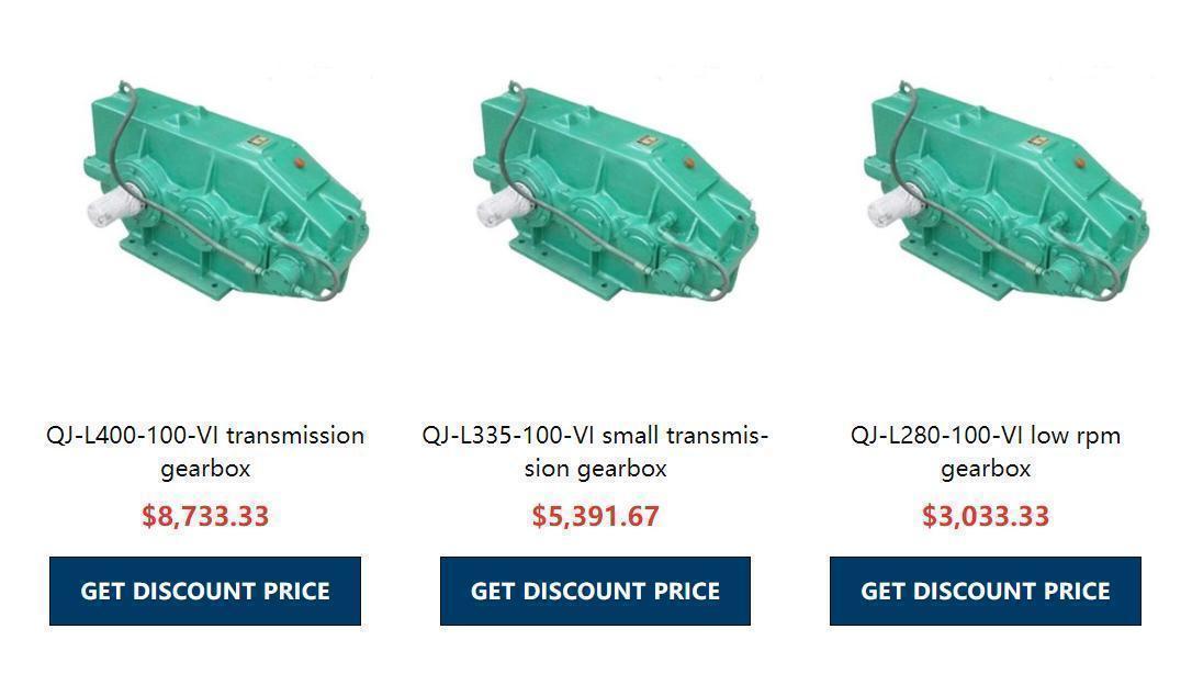
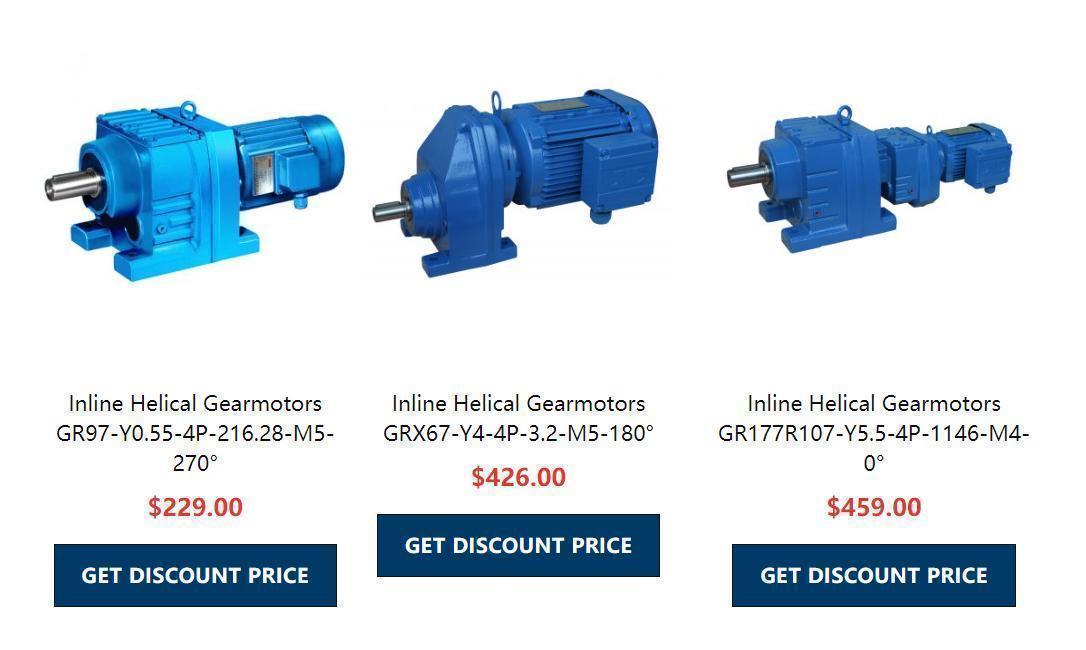
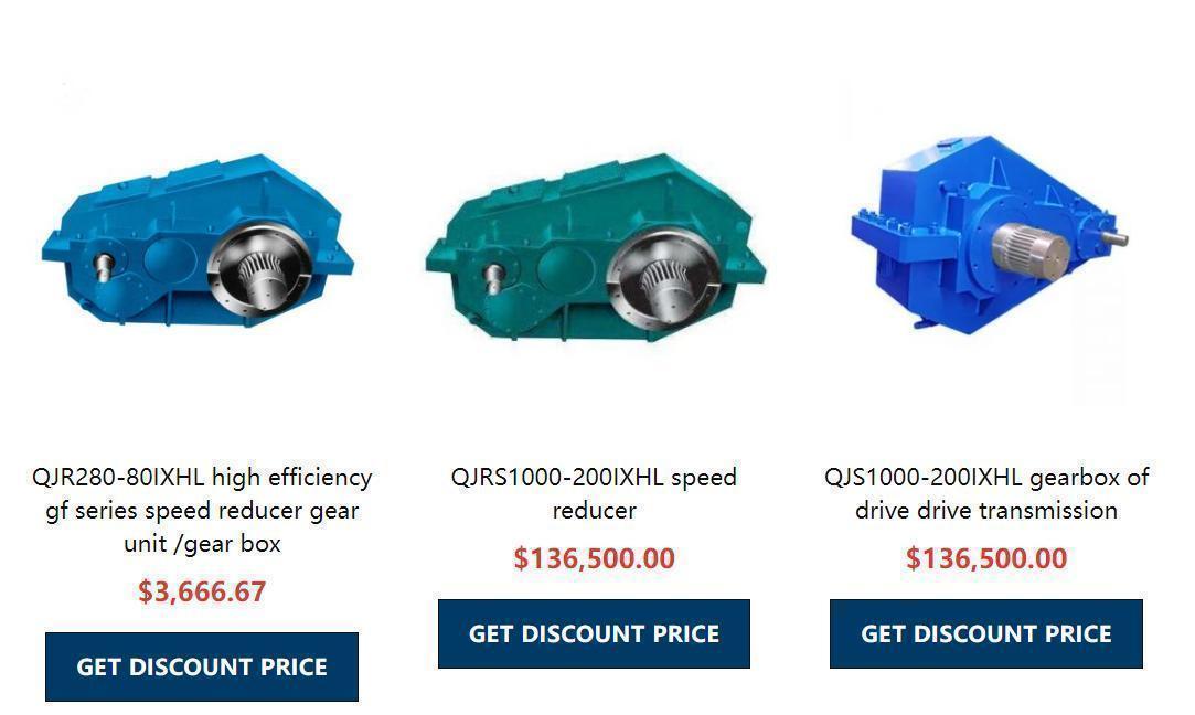
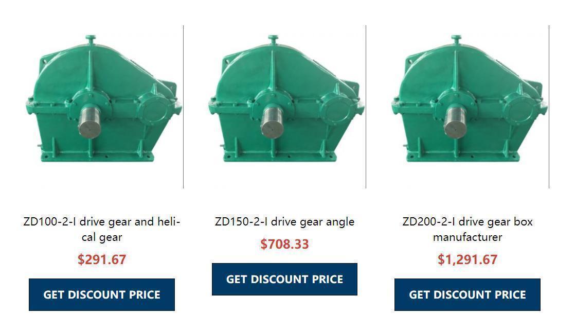
Reducer motor is the integration of reducer and motor (motor).This integration is also commonly referred to as a gear motor or a gear motor.Usually by the professional reducer production plant integrated assembly after complete supply.Deceleration motor is widely used in the iron and steel industry, machinery industry and so on.The advantage of using a reduction motor is to simplify the design and save space.
1. The reducer motor is manufactured according to the international technical requirements with high technological content.
2, space-saving, reliable and durable, high overload capacity, power up to above 95KW.
3, low energy consumption, superior performance, reducer efficiency up to more than 95%.
4, small vibration, low noise, high energy saving, select high-quality section steel material, steel cast iron box body, gear surface after high-frequency heat treatment.
5, after precision processing, to ensure the positioning accuracy, all these constitute the gear reduction motor gear transmission assembly with a variety of motors, the formation of mechanical and electrical integration, fully ensure the use of product quality characteristics.
6. The product adopts the design idea of serialization and modularization and has a wide range of adaptability. This series of products has an extremely large number of motor combinations, installation positions and structural schemes.
Reduction motor classification:
1. High power gear reduction motor
2. Coaxial helical gear reduction motor
3. Parallel shaft helical gear reduction motor
4. Spiral bevel gear reduction motor
5. YCJ series gear reduction motor
Reduction motor is widely used in metallurgy, mining, lifting, transportation, cement, construction, chemical industry, textile, printing and dyeing, pharmaceutical and other general mechanical equipment reduction drive mechanism.
