Low-speed high-torque hydraulic motors refer to hydraulic motors with relatively low speeds but high output torque. They are mainly used in injection machinery, ships, cranes, construction machinery, construction machinery, coal mining machinery, mining machinery, metallurgical machinery, ship machinery, Petrochemical, port machinery, etc.
Working principle:
Crank-link type low-speed high-torque hydraulic motors have been applied earlier, and are known as Staffa hydraulic motors abroad. China's similar model is JMZ, with a rated pressure of 16MPa, a maximum pressure of 21MPa, and a theoretical displacement of up to 6.140r / min.
The low-speed high-torque hydraulic motor consists of a casing, a crank-link-piston assembly, an eccentric shaft, and an oil distribution shaft. Five cylinders are evenly arranged along the circumference in a radial shape inside the casing to form a star-shaped casing; a piston is installed in the cylinder. The piston and the connecting rod are connected by ball twisting. The big end of the connecting rod is made into a saddle-shaped cylindrical tile surface that is closely attached to the eccentric circle of the crankshaft. Together, it rotates with the crankshaft. The pressure oil of the motor passes through the channel of the distribution shaft, and is distributed to the corresponding piston cylinder by the distribution shaft;Among the remaining piston cylinders, the cylinder is in an excessive state, and cylinders 2 and 3 are connected to the drain window. According to the principle of the movement of the crank link mechanism, the plunger affected by the oil pressure acts on the center of the eccentric circle through continuous rush. A force pushes the crankshaft to rotate around the center of rotation, and outputs the rotational speed and torque to the outside. If the inlet and outlet ports are swapped, the hydraulic motor will also rotate in the reverse direction. As the drive shaft and the distribution shaft rotate, the distribution state changes alternately. During the crankshaft rotation, the volume of the cylinder located on the high pressure side gradually increases, while the volume of the cylinder located on the low pressure side gradually decreases. Therefore, during work, the high pressure oil continuously enters the hydraulic motor and is then continuously discharged from the low pressure chamber.

In short, since the orientation of the distribution shaft transition seal interval is consistent with the eccentricity of the crankshaft and rotates at the same time, the oil inlet window of the distribution journal always faces two or three cylinders on one side of the eccentric line, and the suction window faces the eccentric line For the remaining cylinders on the other side, the total output torque is the superposition of the torque generated by all the plungers to the center of the crankshaft, which makes the rotary motion continue.
Cycloidal hydraulic motor is a low-speed motor with a speed range of 10-500 rpm. Motors higher than 500 rpm are high-speed motors. Cycloidal motors have a particularly large displacement due to the special fixed rotor design. This is particularly large compared to gear motors or plunger motors. The displacement of a gear motor is about 200ml / r, which is very large, and the maximum displacement of our cycloid motor is achieved. 1600ml / r, and the minimum displacement of the cycloid motor is now 8ml / r in China, no matter how small it is, and the 8ml / r cycloid motor withstands a maximum pressure of 9MPa, which is relatively small.
Due to the large displacement, a certain amount of hydraulic oil acts on the motor and the output speed is small.
Cycloidal motor is also a type of high torque motor. Due to the large displacement, the same pressure is applied to the cycloidal motor, and the output torque is naturally large. The pressure is about 25MPa. Generally speaking, the rated pressure is 20MPa, which is not small, but some plunger motors can reach 40MPa, which is much larger than the cycloid hydraulic motor.
Due to the low-speed and large-torque characteristics of the cycloid motor, the cycloid motor can maintain a low speed and output a large torque, and can be directly connected to mechanical equipment without the need for an acceleration / deceleration mechanism.
But it does not mean that the cycloid motor can not be added to the reducer. In some special occasions, the combination of the cycloid motor and the reducer can output lower speed and greater torque.
Low-speed high-torque hydraulic motor technical requirements:
① General technical requirements. The nominal pressure series should meet the requirements of GB 2346. The nominal displacement series should meet the requirements of GB 2347. The dimensions of the mounting flange and the shaft extension shall comply with the provisions of GB / T 2353.2.
The type and size of the threaded connection port should comply with the provisions of GB 2878. Other technical requirements shall meet the requirements of 1.2 to 1.4 in GB 7935-87.
Note: The dimensions of the installation flange, shaft extension and oil port of imported products and old products shall be implemented in accordance with relevant regulations.
② Performance
a. Displacement. The no-load displacement should be within the range of 95% to 110% of the geometric displacement.
b. Volumetric efficiency and total efficiency. Under rated operating conditions, volumetric efficiency and total efficiency shall meet the requirements of the following table.
c. Startup efficiency. The minimum starting efficiency at rated pressure shall meet the requirements of the following table.
d. Low-speed performance. Under the conditions of maximum displacement, rated pressure and specified back pressure, the minimum speed of the hydraulic motor should meet the requirements of the following table.
e. noise. The noise value should meet the requirements of the following table.
f. Low temperature performance. There must be no abnormal phenomena during the low temperature test.
g. High temperature performance. There must be no abnormal phenomena during the high temperature test.
h. Overspeed performance. There must be no abnormal phenomena during the overspeed test.
i. External leakage. The static seal must not leak oil; the dynamic seal must not drip oil within 3 hours.
j. Durability. The endurance test is performed according to the following scheme: a full load test of 1000h, a commutation test of 50,000 times, and an overload test of 10h.
Note: Those with special requirements can be carried out according to special technical specifications.
③ Processing quality. According to JB / T 5058 regulations, the importance level of the quality characteristics of processing is divided. For the qualified quality level AQL value, please refer to (2) in (10).
④ Assembly quality. Component assembly technical requirements shall comply with the provisions of 1.5 to 1.8 in GB 7935-87.
a. Air tightness. There shall be no air leakage during the air tightness test.
b. Internal cleanliness. The internal cleanliness assessment method and cleanliness index should meet the requirements of JB / T 7858
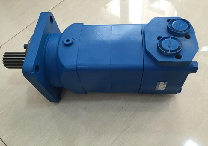
Vulgar high torque hydraulic motor performance:
1. Large starting torque (mechanical efficiency above 0.9 at startup), good stability at low speed, and balanced operation at very low speed.
2. The roller is supported by the roller between the turning and the moving rod, which has high mechanical efficiency.
3. It has a high power-to-mass ratio and relatively small volume and weight.
4. It has an eccentric shaft and a five-piston mechanism with lower excitation frequency, so it has the characteristics of low noise.
5. The plane compensation flow distributor has good reliability, less leakage, and the piston and cylinder bore are sealed by a plastic piston ring, so it has high volumetric efficiency.
6. The direction of rotation can be reversed, and the output shaft can bear radial and axial external forces.
Advanced end flow distribution design, smooth rotation at low speed.
• Advanced shaft seal design can withstand high back pressure.
• Advanced oil distribution mechanism design, with automatic wear compensation function.
• Double-row tapered roller bearing design can withstand large radial forces.
• A variety of flanges, output shafts, and other mounting connections.
Cycloidal motor characteristics:
efficient, smooth operation over the full speed range, constant operating torque, High starting torque, can withstand high oil return pressure without using drain pipe (high pressure consumables), long life even under extreme operating conditions, solid and compact, bearings have high radial and axial load carrying capacity, rust prevention for some parts, can be used in open and closed circuit hydraulic systems, applicable to various hydraulic media
Basic knowledge of hydraulic transmission:
1. Problems with hydraulic transmission
(1) The use of hydraulic transmission has a high demand for protection, and the oil must be kept clean at all times;
(2) High requirements for the manufacturing precision of hydraulic components, complicated processes and high cost;
(3) The repair and repair of hydraulic components is complicated and requires a high level of skill;
(4) Hydraulic transmission is more sensitive to changes in oil temperature, which will affect its stability. Therefore, it is not suitable for hydraulic transmission to work at very high or low temperatures. As usual, the temperature is suitable in the range of -15 ° C to 60 ° C.
(5) In the process of energy conversion, the hydraulic transmission is particularly in the knuckle speed control system, which has a large pressure and a large flow loss, so the system has a low efficiency. Hydraulic motor

2.The advantages of hydraulic transmission:
(1) Small size and light weight. For example, the power hydraulic motor only needs 10% to 20% of the motor. Because the inertial force is small, when it is suddenly overloaded or parked, it will not produce a large blow;
(2) The active conditioning traction rate can be stabilized within a given value, and the stepless speed regulation can be completed, and the speed regulation can be as large as 1: 2000 (usually 1: 100)
(3) Reversing is easy. Without changing the torsional bias of the electromechanical, it can more conveniently complete the reversal of the working mechanism and the conversion of the straight line to and from activities;
(4) The hydraulic pump and the hydraulic motor are connected by oil pipes, which are not strictly limited in terms of space arrangement;
(5) Because the oil is used as the working medium, the components can move smoothly on the outside with relatively little wear, and the service life is long;
(6) Lightweight and restrained, high level of initiative;
(7) Overload protection is easily completed.
(8) The hydraulic components have been standardized, serialized and generalized, which is easy to plan, make and use. Why are the internal structures of hydraulic motors symmetrical?
The main reason why the hydraulic motor has this symmetrical internal structure is that when this product is applied, it needs to be able to achieve forward rotation and reverse rotation. In order to achieve such a rotation, it must be symmetrical in the internal structure, otherwise, it can only perform forward rotation like hydraulic pumps, but not reverse rotation.
It is because the application has different operating requirements for hydraulic motors than hydraulic pumps that require only forward rotation, but requires that they can achieve two different rotations, forward and reverse, so their internal structures are different Due to the requirements of the hydraulic pump, both the internal structure needs to be symmetrical.
In summary, the reason why the internal structure of the hydraulic motor is symmetrical is that when you use this product, you need to rely on the symmetrical internal structure to achieve two different rotations, forward and reverse.

1. Phenomenon
Sudden stops occur when the platform rotates, that is, the rotation is discontinuous. Slow speed, lack of power and other phenomena.
2.Cause analysis
The low-speed large-torque hydraulic motor is an energy conversion device, that is, the input fluid pressure can convert the mechanical energy output. If the efficiency of the pressure motor itself is not considered, the energy input should equal the output. From this point of view, the inability of the hydraulic motor to rotate is necessarily the reduction of the energy input to the hydraulic motor. When the energy is difficult to overcome the resistance of the platform to rotate, a stall occurs.
According to the principle of hydraulic transmission, it is known that the hydraulic motor is rotated by liquid pressure. The hydraulic motor stalls when the control valve is connected to the pressure oil circuit. It must be stopped because the hydraulic pressure of the hydraulic motor plunger cylinder is insufficient to overcome the resistance of the platform. When the accumulated energy is enough to overcome the resistance, the hydraulic motor makes the resistance to jump and rotate, the oil pressure in the system drops sharply, and the motor stops again. This repeatedly forms a platform "crawl" or prevents the hydraulic motor from rotating Excessive resistance causes "crawling". As for the decrease in the flow and working pressure of the input hydraulic fluid, please refer to the analysis and diagnosis of the slow lifting of the boom cylinder.
In short, the "crawling" of the hydraulic motor makes the oil pressure in the system unstable. Most of the oil pressure instability is caused by air in the system. The reason for entering air in the system is the same as the first part.
The reason why the hydraulic motor has too much rotation resistance causes the mechanical efficiency of the motor itself to be low. For example, the resistance of the plunger and the mating friction pair is too large, the friction resistance of the swash plate and the plunger is too large, the friction resistance is too large due to poor bearings, or the mechanical transmission efficiency of the transmission box is low. Or it is caused by too much mechanical friction of the turntable of the platform.
Diagnosis and exclusion:
If the hydraulic cylinder of the hydraulic working device also "crawls", the fault is in the main oil circuit of the hydraulic system, and the diagnosis should be carried out according to the diagnosis method described in the first part of the boom cylinder lifting slowly. After symptomatic elimination.
If the boom hydraulic cylinder of the working device works normally, the "crawling" failure of the hydraulic motor should be at the end of the hydraulic motor and transmission, that is, the mechanical transmission box and platform turntable.
(1) Inspection of hydraulic motor safety valve
Trial the safety valve under the hydraulic motor control valve. Unscrew the safety valve nut, and use an inner hexagonal wrench to rotate the adjustment screw plug, and change the pressure by 2.345 MPa every turn. Therefore, the pressure gauge test should be 9.8MPa. If it is lower than 9.8MPa, it indicates that the “crawling” fault is mostly caused by the set pressure of the hydraulic motor being too low.
(2) Check the hydraulic motor and mechanical transmission part. If the test pressure of the hydraulic motor safety valve is set to 9.8MPs, it means that "crawling" is the excessive mechanical friction resistance from the hydraulic motor to the rotary platform.
Touch the casing of the hydraulic motor with your hand. If you feel hot, it means that the frictional force of the hydraulic motor is too large, which proves that it is the cause of the "crawling" failure and should be ruled out.
If the temperature of the hydraulic motor is normal, you can use the hand mold transmission box and turntable temperature conditions, or observe the lubrication situation. If there are parts with high temperature and poor lubrication, it indicates that most of them are the cause of the “crawling” failure, that is, the friction resistance is too large, which should be ruled out.
Features:
Adopting advanced stator and rotor parameter design, low starting pressure, high efficiency, stable low-speed operation, can withstand higher working pressure, high output torque, advanced shaft seal design, high back pressure bearing capacity, advanced distribution mechanism design, Features of high accuracy of flow distribution and automatic compensation of wear, compact structure, easy to install, allow for series and parallel use, should be connected to the external drain pipe when used in series, adopts tapered roller bearing support design, has a large radial load capacity, making the motor Can be driven directly

When disassembling due to motor failure, please note the following:
1. When disassembling and disassembling, do not carry out in the open air, the disassembly and disassembly site should be clean, and do not damage the joint surfaces. If it is injured, it needs to be repaired before assembly.
2. Wash all parts with gasoline or kerosene before assembling. It is forbidden to use cotton yarn or rags to scrub parts. Use brush or silk cloth. Never immerse the rubber ring in gasoline. After the motor is installed, you need to add 50 to 100 milliliters of hydraulic oil to the two oil ports before installing the machine, and rotate the output oil. If there is no abnormality, install the machine.
3. To ensure the correct rotation direction, pay attention to the positional relationship between the rotor, the small linkage shaft, and the oil distribution plate.
4. The back cover bolts must be tightened alternately multiple times, and the tightening torque is 9 to 10 kgf · m.
1. Standard motor: The flange is near the end of the shaft, which is the connection method of the general motor.
2. Wheel motor: The flange is located in the middle of the motor, in the middle of the internal bearing of the motor, which is more conducive to the bearing capacity of the motor, and can put the entire motor in the wheel, making the installation more compact.
3. Bearingless motor: without output shaft and bearing, the torque is directly output by the spline coupling, which makes the volume smaller and more compact in some special applications. With this motor, the corresponding components must have internal splines suitable for spline couplings.
Finally, the requirements for use:
1. Avoid using the motor at both maximum torque and maximum speed.
2. The torque values listed in the performance parameter table are applicable to 1.75 "diameter shafts and 1.5" output shafts. The maximum continuous and intermittent torque allowed is 1320N.m and 1660N.m.
3. When the allowable back pressure is exceeded, the external drain pipe should be connected, and the inner cavity of the motor can always be filled with hydraulic oil.
4. The maximum inlet pressure and maximum oil return pressure are 31Mpa, but the working pressure difference should meet the requirements in the performance table.
5. The duration of intermittent motor operation is not more than 6 seconds, and the peak operation duration is not more than 0.6 seconds per minute.
6. System maximum working temperature: 82 ℃
