Rotary Encoders measure the number of rotations, the rotational angle, and the rotational position.
The OMRON encoder is a device that compiles and converts signals (such as bit streams) or data into signals that can be used for communication, transmission, and storage.
E6CP-AG5C 256 2M BY OMS, E6B2-CWZ1X 2000P/R 2M BY OMS, E6B2-CWZ1X 2000P/R 2M BY OMS, E6B2-CWZ1X 1000P/R 2M BY OMS, E6B2-CWZ6C 2000P/R 2M BY OMS, E6B2-CWZ6C 1000P/R 2M BY OMS, E6B2-CWZ6C 600P/R 2M BY OMS, E6B2-CWZ6C 360P/R 2M BY OMS, E6A2-CW3C 200P/R 2M, E5EC-RR2ASM-800, E5CC-RX2ASM-001, E5AN-HAA2HH03B-FLK AC100-240
E5AN-HAA2HB AC100-240, E5AC-RX2ASM-000, E3Z-T86-D BY OMC, E3Z-T81A 2M BY OMC, E3Z-T81-L 2M BY OMS, E3Z-T81 2M BY OMC, E3Z-T61-L, E3Z-D61 2M BY OMC, E3X-NH11 2M, E3S-R11 2M, E3S-AD87, E3NX-FA11 2M, E3M-VG12 2M
E3JM-10L BY OMC, E3JM-10L BY OMC, E3JK-DS30S3 2M BY OMS, E3JK-DR12-C 2M OMS, E3JK-DR12-C 2M OMS, E39-R1, E39-L98, E39-L131, E39-L131, E32-ZD11N 2M BY OMS, E32-ZC31 2M BY OMS, E2E-X7D1-N-Z. 2M, E2E-X7D1-N-Z. 2M
E2E-X5ME1-Z. 2M BY OMS, E2E-X5ME1-Z. 2M BY OMS, E2E-X3D1-N 2M, E2E-X3D1-N 2M, E2E-X3D1-M1TGJ-U-Z 0.3M BY OMS, E2E-X2D1-N 2M, E2E-X10ME1-Z. 2M BY OMS, E2E-X10ME1-Z. 2M BY OMS, E2E-S05N03-WC-C1 2M OMS, E2E-CR6C1 2M, E2CY-T11 2M

1. Incremental
Incremental Encoders output a pulse string according to the rotational displacement of an axis. The number of rotations can be detected by counting the number of pulses.
1) E6A2-C
Compact Encoder with External Diameter of 25 mm
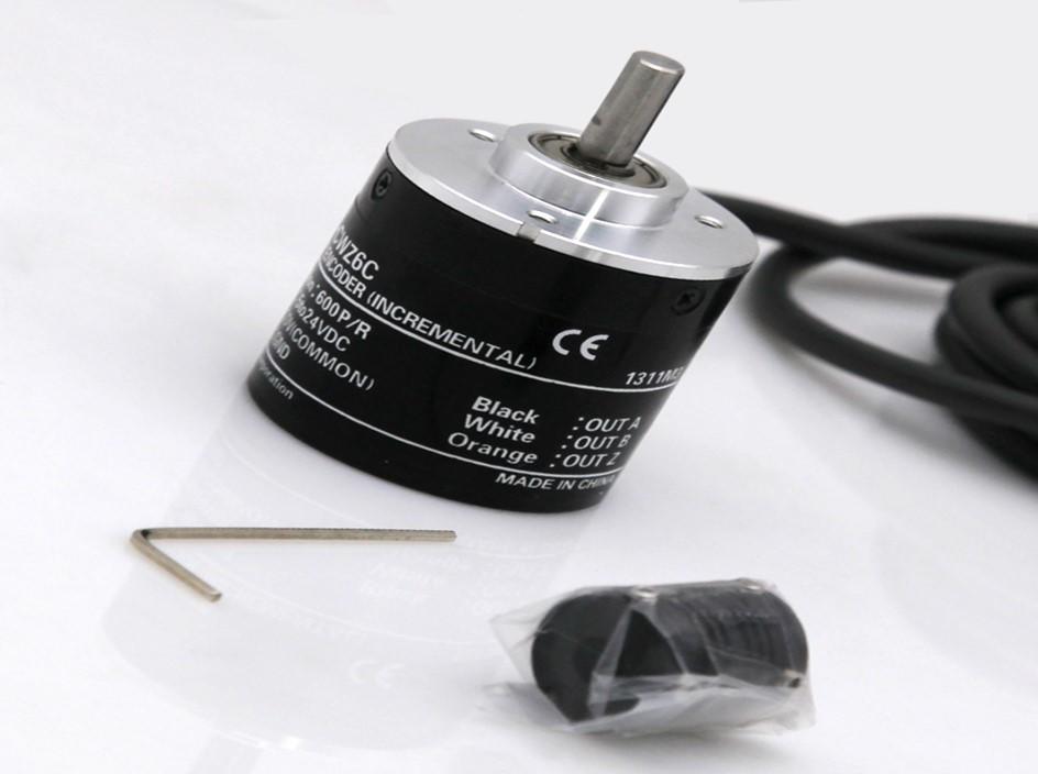
2) E6B2-C
General-purpose Encoder with External Diameter of 40 mm. • Incremental model • External diameter of 40 mm. • Resolution of up to 2,000 ppr.
3) E6C2-C
General-purpose Encoder with External Diameter of 50 mm.
• Incremental model
• External diameter of 50 mm.
• Resolution of up to 2,000 ppr.
• IP64 (improved oil-proof construction with sealed bearings)
• Side or back connections are possible. Pre-wired Models with cable connected at an angle.
2. Absolute
Absolute Encoders output the rotational angle using an absolute code. The rotational position can be detected by reading the code. This eliminates the need to return to the origin at startup.
1) E6CP-A
General-purpose Absolute Encoder with External Diameter of 50 mm
• Absolute model.
• External diameter of 50 mm.
• Resolution: 256 (8-bit).
• Lightweight construction using plastic body.
2) E6C3-A
• Absolute model.
• External diameter of 50 mm.
• Resolution of up to 1,024 (10-bit).
• IP65 (improved oil-proof protection with sealed bearings)
• Optimum angle control possible in combination with PLC or Cam Positioner.
3) E6F-A
• Absolute model.
• External diameter of 60 mm.
• Resolution of up to 1,024 (10-bit).
• IP65 oil-proof protection.
• Strong shaft.

3. Direct Discrimination Unit
A Direction Discrimination Unit accepts phase difference signal from the Encoder to detect the direction of rotation. Either voltage or open-collector outputs can be connected.
1) E63-WF
• Input phase difference signal from the Encoder to detect the direction of rotation.
• High-speed response at 120 kHz.
• Mounts to DIN Track. Thin design enables superb mounting efficiency.
• Front-panel switch enables reversing phase Z logic. Enables connecting either voltage outputs or open-collector outputs.
4. Peripheral Devices
Accessories required by Rotary Encoders are provided, including Couplings, Flanges, and Servo Mounting Brackets.
Introduction:
Omron (OMRON) encoder is a well-known encoder developed by Omron Group.
The encoder converts the angular displacement or linear displacement into an electrical signal. The former becomes a code disk, and the latter is called a code ruler. The encoder can be divided into two types: contact type and non-contact type according to the reading method. The contact type adopts the brush output. A brush contacts the conductive area or the insulating area to indicate whether the status of the code is "1" or "0"; the non-contact type receiving sensitive element is a photosensitive element or a magnetic sensitive element. The translucent area and the opaque area indicate whether the status of the code is "1" or "0", and the collected physical signals are converted into electrical signals readable by the machine code through the binary coding of "1" and "0" Used for communication, transmission and storage.
Omron (OMRON) encoder is a device used to measure the rotational speed. The photoelectric rotary encoder can convert the mechanical displacements such as the angular displacement and angular velocity of the output shaft into corresponding electrical pulses by digital output (REP) through photoelectric conversion. It is divided into single output and dual output. The technical parameters mainly include the number of pulses per revolution (dozens to thousands), and the power supply voltage. Single output means that the output of the rotary encoder is a set of pulses, and the dual output rotary encoder outputs two sets of pulses with a 90 ° phase difference between A / B. The two sets of pulses can not only measure the speed, but also determine the rotation Direction. Omron OMRON is close to the open one. Working principle: The proximity switch is composed of three parts: oscillator, switch circuit, and amplified output circuit. The oscillator generates an alternating magnetic field. When the metal target approaches this magnetic field and reaches the sensing distance, an eddy current is generated in the metal target, which oscillates and even stops. The changes of oscillator oscillation and vibration stop are processed by the post-stage amplifier circuit and converted into switches to trigger the drive control device to achieve the purpose of non-formal detection. The closer the target is to the sensor and the closer the target is to the sensor, the greater the damping in the coil: the greater the damping, the smaller the current of the sensor oscillator is the current loss of the inductive proximity switch.
Encoder signal output:
(1) The signal output has sine wave (current or voltage), square wave (TTL, HTL), open collector (PNP, NPN), push-pull type, and TTL is long-line differential drive (symmetric A, A-; B, B-; Z, Z-), HTL is also called push-pull and push-pull output, the signal receiving device interface of the encoder should correspond to the encoder. Signal connection-The pulse signal of the encoder is generally connected to the counter, PLC, and computer. The module connected between the PLC and the computer is divided into a low-speed module and a high-speed module, and the switching frequency is low and high. Such as single-phase connection, used for unidirectional counting and unidirectional speed measurement. A.B two-phase connection is used for forward and reverse counting, judgment of forward and reverse and speed measurement. A, B, Z three-phase connection, used for position measurement with reference position correction. A, A-, B, B-, Z, Z- connection, due to the connection with symmetrical negative signal, the electromagnetic field contributed by the current to the cable is 0, the attenuation is minimum, the anti-interference is the best, and it can transmit a long distance. For TTL encoders with symmetrical negative signal output, the signal transmission distance can reach 150 meters. The rotary encoder is composed of precision devices, so when subjected to a large impact, it may damage the internal function, and care should be taken when using it. Installation Do not apply direct impact to the shaft during installation. A flexible connector should be used to connect the encoder shaft to the machine. When installing the connector on the shaft, do not press it hard. Even if a connector is used, due to poor installation, a load greater than the allowable load may be applied to the shaft, or a core pulling phenomenon may occur, so pay special attention. Bearing life is related to service conditions and is particularly affected by bearing load. If the bearing load is less than the specified load, the bearing life can be greatly extended. Do not disassemble the rotary encoder. Doing so will damage oil and drip resistance. Anti-drip products should not be immersed in water and oil for a long time. Wipe clean when there is water or oil on the surface.

(2) Vibration Vibration added to the rotary encoder is often the cause of false pulses. Therefore, attention should be paid to the installation place and installation place. The greater the number of pulses per revolution, the narrower the slot spacing of the rotating slot disk, and the more susceptible it is to vibration. When rotating or stopping at a low speed, the vibration applied to the shaft or the body makes the rotating groove disc shake, and false pulses may occur.
(3) About wiring and connection Incorrect wiring may damage the internal circuit, so pay full attention to the wiring:
1. Wiring should be carried out with the power OFF. When the power is turned on, if the output line contacts the power, the output circuit may be damaged.
2. If the wiring is wrong, the internal circuit may be damaged, so pay attention to the polarity of the power supply when wiring.
3. If it is wired in parallel with the high-voltage line and the power line, it may be damaged by induction and malfunction, so separate the wiring.
4. When extending the wire, it should be less than 10m. And due to the distribution capacity of the wire, the rise and fall time of the waveform will be longer. If there is a problem, the Schmitt circuit or the like is used to shape the waveform.
5. In order to avoid induced noise, etc., use the shortest distance wiring as much as possible. Pay special attention when importing into integrated circuits.
6. When the wire is extended, due to the influence of the conductor resistance and the capacitance between the wires, the rise and fall times of the waveform are prolonged, which is likely to cause interference (crosstalk) between the signals. , Shielded wire). For HTL encoders with symmetrical negative signal output, the signal transmission distance can reach 300 meters.
The working principle of the encoder:
A photoelectric code wheel with an axis in the center, which has a ring-shaped, dark score line, read by photoelectric transmitting and receiving devices, and obtains four sets of sine wave signals combined into A, B, C, D, each sine wave The phase difference is 90 degrees (360 degrees relative to a cycle), the C and D signals are reversed and superimposed on the A and B phases to enhance the stable signal; another Z phase pulse is output per revolution to represent the zero reference Bit. Since the two phases of A and B differ by 90 degrees, the forward and reverse rotation of the encoder can be judged by comparing phase A or phase B. The zero reference position of the encoder can be obtained through the zero pulse. The material of the encoder code disc is glass, metal, plastic. The glass code disc is a thin line deposited on the glass. It has good thermal stability and high precision. The metal code disc is directly engraved with or without engraved lines, which is not fragile. However, because the metal has a certain thickness, the accuracy is limited, and its thermal stability is an order of magnitude worse than that of glass. The plastic code wheel is economical and its cost is low, but the accuracy, thermal stability, and life are all worse. . Resolution-The number of pass or dark lines provided by the encoder per 360 degrees of rotation is called resolution, also known as resolution indexing, or how many lines are directly called, generally 5 to 10000 lines per revolution.
The advantages of the encoder:
From proximity switches, photoelectric switches to rotary encoders. Positioning in industrial control, the application of proximity switches and photoelectric switches is quite mature, and it is very easy to use.
The advantages of the encoder:
From proximity switches, photoelectric switches to rotary encoders. Positioning in industrial control, the application of proximity switches and photoelectric switches is quite mature, and it is very easy to use.

Encoder function:
A measuring element that converts the relative displacement between two planar windings into an electrical signal using the principle of electromagnetic induction and is used in length measuring tools. Induction synchronizers (commonly known as encoders and grating scales) are divided into linear and rotary types. The former is composed of fixed length and sliding ruler for linear displacement measurement; the latter is composed of stator and rotor and is used for angular displacement measurement. In 1957, R.W. Tripp and others in the United States obtained a patent for an induction synchronizer in the United States. The original name was a position measuring transformer, and the induction synchronizer was its trade name. It was initially used for positioning and automatic tracking of radar antennas and missile guidance. In mechanical manufacturing, induction synchronizers are often used in positioning feedback systems for digitally controlled machine tools, machining centers, etc. and in digital measurement display systems for coordinate measuring machines, boring machines, etc. It has low requirements on environmental conditions and can work normally in a small amount of dust and oil mist. The period of the continuous winding on the fixed length is 2 mm. There are two windings on the sliding ruler, and the period is the same as that on the fixed ruler, but they are staggered by 1/4 cycle (electrical phase difference 90 °). There are two types of inductive synchronizer: phase detection type and amplitude detection type. The former is to input two AC voltages U1 and U2 with a phase difference of 90 ° and the same frequency and amplitude into the two windings on the slide rule respectively. According to the principle of electromagnetic induction, the winding on the fixed scale will generate an induced potential U. If the slide rule moves relative to the fixed scale, the phase of U changes accordingly. After magnification, compare with U1 and U2, subdivide and count, the displacement of the slide rule can be obtained. In the amplitude discrimination type, the input slider windings are AC voltages with the same frequency and phase but different amplitudes, and the displacement of the slider can also be obtained according to the amplitude changes of the input and output voltages. The system composed of inductive synchronizer and electronic parts such as amplification, shaping, phase comparison, subdivision, counting, display and so on is called inductive synchronizer measurement system. Its length measurement accuracy can reach 3 microns / 1000 mm, and its angle measurement accuracy can reach 1 ″ / 360 °.
Encoder classification:
E6A2 encoder
☆ Φ25 is a small economic type.
☆ Low and medium resolution type.
☆ Voltage: 5-12V or 12-24V.
☆ Output signal: Phase A
☆ Output form: collector, voltage
E6B2 encoder
☆ Dimensions: Ф40 * 30.
☆ Shaft diameter: Ф6 / D type incision.
☆ Number of pulses: 60P / R-2000P / R.
☆ Voltage: 5-12V or 12-24V.
☆ Output signal: A phase, B phase, Z phase.
☆ Output form: collector, voltage, long-term drive
E6C2 encoder
☆ Φ50 universal type,
☆ Low and medium resolution type
☆ Protection structure IP64f (anti-drip and anti-oil);
☆ NPN, PNP output, line drive output;
☆ Enhance anti-sag performance.
Difference between incremental encoder and absolute encoder:
The incremental encoder outputs a pulse signal, and the absolute encoder outputs an absolute value.
Absolute encoders are divided into single-rotation absolute type and multi-rotation absolute type. The single-rotation absolute encoder can only record the value corresponding to each angle in one circle, and cannot record the number of circles; the multi-rotation absolute encoder can not only record the value corresponding to each angle in one circle, but also record the rotation. A few laps, so it will have two output lines, one to record the number of laps, and one to record the data for each revolution.
The encoder is connected to the subsequent equipment (such as PLC), and the data is monitored in the input channel of the PLC. If the encoder is an incremental encoder, all data in the channel is cleared when the PLC is powered off and then on; if it is an absolute encoder, The original data remains in the channel (provided that the axis of the encoder has not been rotated after power off).

The resolution is also known as the number of digits, the number of pulses, and the number of lines (this will be called in absolute encoders). For incremental encoders, it is the number of pulses output by the encoder for one revolution of the shaft; for absolute encoding For the device, it is equivalent to dividing a circle of 360 ° into equal parts. For example, if the resolution is 256P / R, it is equivalent to dividing a circle of 360 ° into 256, and a code value is output for every 1.4 ° of rotation. The unit of resolution is P / R.
OMRON-Omron encoder --- Omron series
The Omron Group was founded in 1933. Mr. Tachiishi established a small factory called Tachiishi Electric Works in Osaka. At that time, there were only two employees. In addition to the production of timers, the company initially specialized in the production of protective relays. The manufacture of these two products became the starting point of Omron Corporation. As of March 31, 2012, there were 35,992 employees, # turnover was 619.5 billion yen, and the product variety reached hundreds of thousands, involving industrial automation control systems, electronic components, automotive electronics, social systems, and health and medical equipment. field. Since its establishment on May 10, 1933, through continuous creation of new social needs, Omron Group has taken the lead in the development and production of contactless proximity switches, electronic automatic sensor signals, vending machines, automatic ticket inspection systems at stations, and automatic diagnosis of cancer cells A series of products and equipment systems have contributed to the progress of society and the improvement of human living standards. At the same time, Omron Group has rapidly developed and grown automated control and electronic equipment manufacturers, and has mastered the core technologies of sensing and control.


