Selection and use of gearbox for speed reducer, how to select the right motor gearbox
First, the selection guide is for various of gearbox for speed reducer
In order to select a suitable gearbox for speed reducer, it is necessary to know the detailed technical characteristics of the machine driven by the gearbox for speed reducer. It is necessary to determine a use factor Fb, using the factor Fb.
The selection of the gearbox for speed reducer should first determine the technical parameters: the number of working hours per day; the number of starts and stops per hour; the hourly running cycle; the reliability requirement; the working machine torque T working machine; the output speed n out; the load type; the ambient temperature; On-site heat dissipation conditions;
gearbox for speed reducer is usually designed according to the constant torque, infrequent start and stop, and normal temperature.
The allowable output torque T is determined by the following formula:
T=T out X FB usage factor
T out---------- gearbox for speed reducer output torque, FB------- gearbox for speed reducer use coefficient
Transmission ratio ii=n In / n output motor power P (KW) P = T out * n out / 9550 * η Output torque T out (Nm) T out = 9550 * P * η / n in the formula: n into - input speed η - transmission efficiency of gearbox for speed reducer
When selecting a gearbox for speed reducer, according to different working conditions, the following conditions must be met: 1. T out ≥ T working machine 2. T = FB total * T working machine
Where: FB total - total usage factor, FB total = FB * FB1 * KR * KW FB - load characteristic coefficient, KR - reliability factor FB1 - coefficient of environmental question;

Second, gearbox for speed reducer installation precautions
When installing gearbox for speed reducer, the center of the drive shaft should be centered, and the error should not be greater than the compensation amount of the coupling used. Good alignment can extend the service life and achieve the desired transmission efficiency. When installing the transmission member on the output shaft, it is not allowed to strike with a hammer. Usually, the internal friction of the assembly jig and the shaft end is used, and the transmission member is pressed by the bolt, otherwise the internal parts of gearbox for speed reducer may be damaged. It is better not to use a steel fixed coupling. Due to the improper installation of this type of coupling, it will cause unnecessary external load, which will cause early damage of the bearing, and even cause the output shaft to break.
gearbox for speed reducer should be firmly installed on a stable level foundation or base. The oil in the oil drain should be removed, and the cooling air circulation should be smooth, the foundation is unreliable, vibration and noise will be caused during operation, and the bearings and gears will be damaged. When the transmission joint has protrusions or gears or chains, it should be considered to install protective devices. When the output shaft is subjected to large radial loads, the reinforcement type should be selected.
According to the specified installation device, the staff can conveniently approach the oil mark, vent plug and drain plug. After the installation is in place, the accuracy of the installation position should be thoroughly checked in order, and the reliability of each fastener should be flexibly rotated after installation. gearbox for speed reducer is splashed and lubricated in the oil pool. Before running, the user needs to remove the bolt of the vent hole and replace it with a vent plug. According to different installation positions, and open the oil level plug screw to check the height of the line, refuel from the oil level plug until the oil overflows from the oil level plug screw hole, and screw the oil level plug to ensure that it is empty. Commissioning, the time must not be less than 2 hours. The operation should be stable, no impact, vibration, noise and oil leakage. If abnormalities are found, they should be eliminated in time.

After a certain period of time, the oil level should be checked again to prevent possible leakage of the casing. If the ambient temperature is too high or too low, the grade of the lubricating oil can be changed.
Third, the installation of shaft mounted gearbox for speed reducer.
1. Connection between gearbox for speed reducer and working machine
gearbox for speed reducer is directly set on the working machine main shaft. When gearbox for speed reducer is running, the counter torque acting on the deceleration housing is mounted on the counter-torque bracket on the deceleration housing or balanced by other methods. The machine directly matches the other end. Connected to a fixed bracket
2. Installation of the anti-torque bracket
The anti-torque bracket is mounted on the side of gearbox for speed reducer facing the working machine to reduce the bending moment attached to the working machine shaft.
The bushing of the anti-torque bracket and the fixed support coupling end uses an elastic body such as rubber to prevent deflection and absorb the torque ripple generated.
3. Installation relationship between gearbox for speed reducer and working machine
In order to avoid deflection of the working machine spindle and additional force on gearbox for speed reducer bearing, the distance between gearbox for speed reducer and the working machine should be as small as possible without affecting normal working conditions, and its value is 5-10mm.

Fourth, the inspection and maintenance of gearbox for speed reducer
The newly-introduced gearbox for speed reducer has been injected into the L-CKC100L-CKC220 medium-pressure industrial gear oil in GB/T5903 at the factory. After 200-300 hours of operation, the first oil change should be carried out, and should be used in the future. Regularly check the quality of the oil and replace it with oil that has been mixed into the magazine or deteriorated.
Under normal circumstances, for gearboxes that work continuously for a long time, replace the new oil with 5000 hours of operation or once a year. The gearbox that has been deactivated for a long time should be replaced with new oil before re-running. gearbox for speed reducer should be added to the same grade as the original grade. Oil should not be mixed with oils of different grades. Oils with the same grade and different viscosity are allowed to be mixed.
When changing oil, wait for gearbox for speed reducer to cool down without burning danger, but still keep the oil temperature. Because the viscosity of the oil increases after complete cooling, it is difficult to drain the oil. Mainly: cut off the power supply of the transmission to prevent unintentional energization!
During work, when the temperature rise of the oil exceeds 80 °C or the temperature of the oil pool exceeds 100 °C and the noise of the production is abnormal, stop using it and check the cause. It is necessary to troubleshoot and replace the lubricant before continuing operation.
The user shall have reasonable rules for the use and maintenance, and shall carefully record the operation of gearbox for speed reducer and the problems found during the inspection. The above provisions shall be strictly implemented.
Selection of lubricating oil
gearbox for speed reducer must be filled with lubricating oil of appropriate viscosity before it is put into operation. The friction between the gears must be reduced. When the load is high and the load is high, gearbox for speed reducer can fully exert its function.
First use for about 200 hours, the lubricant must be drained, rinsed, and then re-added new lubricant to the center of the oil standard. If the oil level is too high or too low, it may cause the operating temperature to decelerate the training materials.

First, the commonly used formula:
1. Line speed V(m/s): V=Л*D*N/60(m/s);
2. Torque (torque) T(N.m): T=F*R(N:m) or T=F*D/2(N.m)
3. Torque T (N.m) (related to power speed):
T= *η(N.m) or P= (N.m)
4. Synchronous speed of AC motor No. (r/min or r.p.m): No=
Code: Л—3.14, D—diameter (mm), R—radius (mm), V—linear velocity (m/s), F—force (N), P—power (KW), f—power frequency (Hz), P - the number of poles of the motor.
Second, Fengxin Company produces six series of gearbox for speed reducer:
1. Cycloidal pinwheel gearbox for speed reducer;
2. G series hardened surface reducer (GR, GS, GK, GF) and PV series universal gearbox;
3, hard tooth machine cylindrical reducer ZD (L, S, F) Y;
4. Conical cylindrical gearbox for speed reducer MBY(K), MCYK
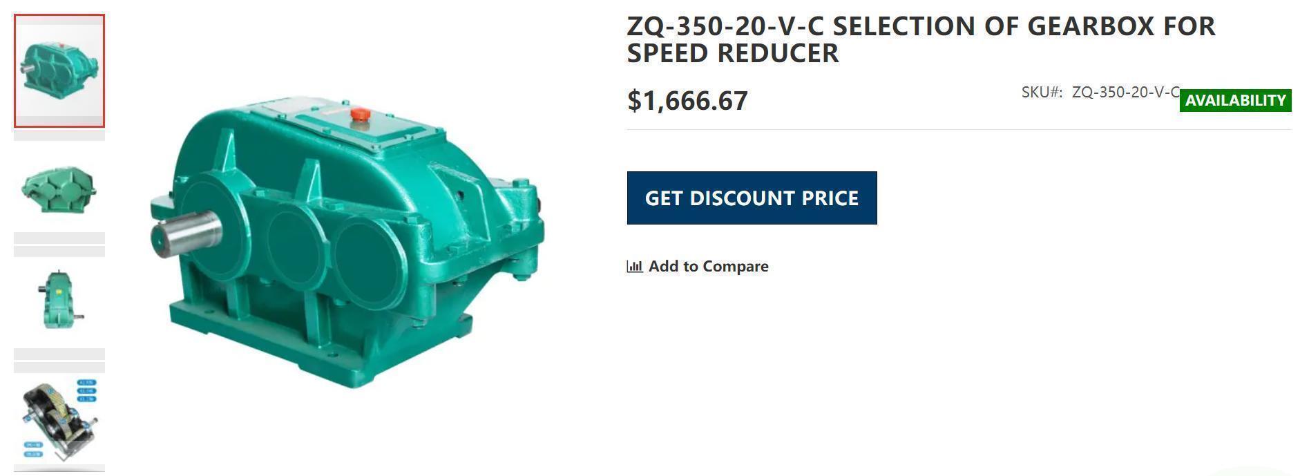
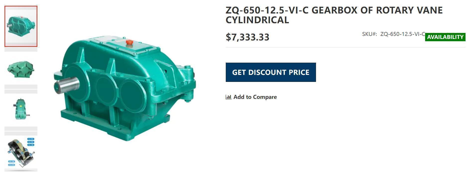
5, ZQ, ZD (L, S) soft tooth surface and ZQA, QJ, ZD (L, S) Z, DB (C) Z hard surface reducer;
6, electric drum.
Third, cycloidal pinwheel reducer (execution standard: JB/T2982-94A/B JB2982-81)
1. Structural principle (sample Pg1);
2, characteristics (sample Pg1);
3. Scope of application: a. The speed of the high speed shaft is not more than 1500 rpm;
b, working environment -100∽400;
c, the temperature rise is less than 600, and the maximum temperature is not more than 800;
4, use and lubrication (sample Pg20, 21);
5. Main parts, materials and strength:
a, cycloidal wheel GCr15, heat treatment quenching hardness HRC 58∽62;
b, output shaft, input shaft 45#, heat treatment quenching and tempering HB 230∽260;
c, base HT200;
6, the cycloid wheel processing process:
Forging (GCr15) Spheroidizing Annealing Roughing Cars Refining Finishing Cars Drilling Holes and Other Holes Hobbing Quenching (HRC58∽62) Grinding End Face Grinding Large Inner Hole Grinding Equal Holes Rough Grinding Fine Grinding Teeth;

Fourth, should have the common sense:
1. Single stage speed ratio: 11, 17, 23, 29, 35, 43, 59, 71, 87;
2, model method: single-stage, multi-stage, with motor, input shaft type;
3, the main parts material (frame, cycloid, shaft) and strength;
4. Lubrication method, lubricant grade, replacement time;
5, installation precautions;
6, can quickly find the main installation size and dimensions of the sample (including the specifications of consumables);
7, the correct selection.
Fifth. Standard comparison table of cycloid reducer:
Standard type of gearbox for speed reducers:
JB/T2982-94A X1 X2 X3 X4 X5 X6 X7 X8 X9 X10 X11 X12
JB/T2982-94B B09 B0 B1 B2 B3 B4 B5 B6 B7 B8 B9
JB2982-81 B15 B18 B22 B27 B33 B39 B45 B55 B65
Ministry of Chemical Industry Standard B120 B150 B180 B220 B270 B330 B390 B450 B550 B650
Sixth, G series hard surface gearbox for speed reducer (GR, GS, GK, GF);
1. Characteristics: G series hard tooth surface reducer is similar to German SEW company product design, modular design, unrestricted installation position, high overall strength, high efficiency, small size, low noise, long life and can withstand larger diameters. Direction load
a. Highly modular design: It can be easily equipped with various types of motors or other power sources. The same type of machine can be equipped with motors of various powers, which is easy to realize the combined connection between various models;
b. Installation form: three-dimensional installation (M1-M6) can be realized;
c. High overall strength: the box body is made of high-strength cast iron, once integrated, the gear is made of high-quality alloy steel (20CrMnTi), carburizing and quenching fine grinding process, precision 5-6, hardness HRC58-62;
d. Efficiency: first-class transmission: 98%; secondary transmission: 96%; three-stage transmission 94%; worm gear: 62-77%;
e. Life: design life is more than 36000 hours (even and smooth load);
f. Use environment: -100C-400C; below 1000 meters above sea level, can run in reverse direction;
g. axial force: an axial force not greater than 5% of the radial load;
2. Electric Motor: equipped with Y2 series motor, according to IP54 protection grade, used according to Class B insulation;
3. Lubrication: The gear unit has been lubricated at the factory. The lubricating oil used is GR, GK, GF medium load gear oil (L-CKC-220 or 320), GS: worm gear oil (L-CKE/P) ;
4. Heat treatment of main parts materials:
a. Gear: 20CrMnTi (forging), carburizing and quenching HRC58-62
b. Shaft: 20CrMnTi (forging), carburizing and quenching HRC58-62
c. Worm: 20CrMnTi, carburized and quenched HRC58-62
d. Output shaft: 42CrMo, quenched and tempered HB240∽286
5, the processing process of the main parts:
a. Box: Metal mold mechanical molding Casting Artificial aging treatment Shot peening Processing center processing (Japan) Three-coordinate detector inspection (Japan)
b. Gear: Forging Rough car Normalizing treatment Finishing car (CNC lathe) Hobbing Carburizing and quenching and tempering (HRC58-62)
Shot peening (including root) Grinding end grinding inner hole end chamfering coarse grinding tooth fine grinding tooth 6 (German CNC forming gear grinding machine) Gear detection center detection (tooth shape, tooth direction, pitch, etc.) Magnetic particle inspection Wire cutting keyway
c. Shaft: Forging Rough car Normalizing treatment Finishing car (CNC lathe) Hobbing Milling keyway Carburizing and quenching
Shot peening (including roots) Grinding center hole Grinding outer circle Rough grinding teeth Fine grinding teeth 6 (German CNC forming gear grinding machine)
Gear detection center detection (tooth shape, tooth direction, pitch, etc.) Magnetic particle inspection

6, classification:
a.GR series helical gearbox for speed reducer
Primary helical gear GRX:
Features: parallel shaft output, small speed ratio, center height, and efficiency 98%;
Parameters: frame number RX57∽107 (6 types); power 0.12-45KW; speed ratio 1.3∽6.63; output torque 16∽830N.m
Second and third grade helical gear GR:
Parameters: frame number R17∽167 (13 types); power 0.12∽160KW; speed ratio 3.37∽289.74; output torque 100∽18000N.m
b, GS series helical gear - worm gearbox for speed reducer:
Features: large speed ratio, high and low center, low efficiency (speed ratio less than 70, efficiency 77%; speed ratio greater than 70, efficiency 62%)
Parameters: frame number GS37∽97 (7 types); power 0.12∽30KW; speed ratio 7.57∽288; output torque 17∽4200N.m
c, GK series helical gear - spiral bevel gearbox for speed reducer:
Features: vertical output; high transmission torque; high gear accuracy; efficiency 94%
Parameters: frame number GK37∽187 (12 types); power 0.12∽200KW; speed ratio: 5.36∽197.37; output torque 9.9∽50000N.M
d, GF series parallel shaft helical gearbox for speed reducer:
Features: Parallel output; efficiency 94∽96%
Parameters: frame number GF37∽157 (10 types); power 0.12∽110KW; speed ratio 3.77∽281.71; output torque 3.3∽18000N.m

7, selection:
Constant power situation:
1 Known power P, input speed n1, output speed n2 (or speed ratio), working condition coefficient fA, can be directly checked (selection parameter table, constant power):
Find the corresponding power, the similar speed ratio, compare the use factor fB ≥ fA, but when the input speed is not 1500r.p.M, the power Pn should be converted:
Pn=(1500/n1)P, and it is sufficient to satisfy fB≥fA with the PN lookup table.
Example 1: Y2 motor, P=1.5KW, 4 pole, speed ratio i=37, working condition coefficient fA=2, parallel output (small eccentricity), with foot and horizontal output, select the appropriate model;
Solution: Model GR, check sample PgR19, select GR77, i=36.83, fB=2.2>fA, can be used, machine model: GR77-Y1.5-4P-36.83-M1
Example 2: Input power 3.2KW, n1=500r.p.m, n2=20r.p.m, fA=1.5, GR double-axis type, input shaft shaft diameter is Φ38, foot mounting, output shaft facing down, select the appropriate model;
Solution: n1=500r.p.m, not 1500r.p.m to convert power
PN=(1500/n1)*P=1500/500*3.2=9.6KW Select 11KW
Check the table PgR30, get GR97, fB=1.55, i=25.03, fB>fA=1.5, the machine model: GRSZ97AD4-25.03-M4

2 known working torque M2, working speed n2, working condition coefficient fA
Method: The motor pole number is not specified. The 4-pole motor is used first, and the motor power is calculated: P=M2*n2/9550, and the speed ratio i=n1/n2 is determined.
Calculate M2*fA and press M2*fA≤Ma, the primary model
According to the power, speed ratio and primary selection model, check the parameter list (constant power), find Ma, fB
Test Ma*fB≥M2*fA (for worm gears, must be Ma>M2)
Example 3: M2=1200N.m, n2=30r.p.m, fA=1.2, vertical output, hollow shaft, flange installation, installation form M3, efficiency greater than 90%, suitable for the model;
Solution: The 4-pole motor is not specified, and the model is GKAF.
P=M2*n2/(9550*η)=1200*30/9550*0.94=4KW, M2*fA=1200*1.2=1440N.m
The primary selection specification is GKAF77, and the lookup table PgK17 is: i=45.24, fB=1.3, Ma*fB=1140*1.3=1482N.m>M2*fA=1440N.m meets the requirements
Machine model: GKAF77-Y4-45.24-M3
Example 4: Steel mill wire drawing machine (24-hour working system), the power required for driving equipment is 13KW, frequency conversion speed regulation is required, input and output vertical direction, base is horizontally installed, motor junction box and one-way output shaft are seen at the end of the motor, respectively And to the right, the output speed of the shaft is about 23 rpm, the start and stop is less than 10 times per hour, the ambient temperature is about 250C, and the radial load acts on the center of the shaft, about 3.5 tons.
Solution: From the known conditions, the working condition coefficient table fah=1.75, fac=1, fat=1, fA=fah*fac*fat=1.93
Vertically formulate GK models based on input and output:
M2=9550*P1/n1=9550*13/23=5398N.m, M2*fA=5398*1.93=10413N.m, P≥P1/n=13/0.94=13.8KW Select 15KW
Look up table PgK21 to get Ma=5808N.m, fB=2.1 GK127 Ma*fB=5808*2.1=12196N.m>M2*fA=10418N.m
Determine the radial load: FX=Fr*fA=35000*1.93=67550N
Checked: GK127 machine Fra=76000N>Fx=67550N, optional machine model: GK127-YVP15-4P-62.31-M1-B-2700
8, G series supplementary instructions:
a. GK, GKAB are the same box, GKA, GKAF, GKAT are the same box, and the above two boxes are different in size;
b. There are two types of hollow shaft diameters of GSA, GSAF and GSAZ;
c. GRF, GRXF, GRM output flange size has a variety of to be marked;
d. Input shaft type input shaft shaft diameter has a variety of to be marked;
e. Dimensional tolerance: center height.h≤250—- -0.5 h>250—- -1
Axis diameter.ΦD≤50—- R6 ΦD>50—m6
Hollow shaft. Inner hole diameter - H7
9, G series should have common sense:
a. Each series of models, the approximate output torque range, power range, speed ratio range;
b. accurate model representation;
c. Main part materials (box, gear, pinion) and strength;
d. Lubrication method, lubricant grade, replacement time (when the ambient temperature is lower than 00, preheat before starting);
e. Installation precautions;
f. Quickly find the main installation dimensions and dimensions on the sample;
g. Determine the model of the machine accurately according to the actual situation;
h. Familiar with the processing technology of main parts (box, gear, pinion);
i. The input speed of the high speed shaft is not more than 1500r.p.m, and the line speed is not more than 20m/s.
7. Hardened cylindrical gear (JB/T8853-2001) and conical cylindrical gearbox for speed reducer (JB/T9002-1999):
1. Characteristics: In the 70s, the design of similar products of Flanders is not simulated. Compared with the soft tooth surface, the bearing capacity is greatly improved, the efficiency is high, the volume is small, the service life is long, the single-stage efficiency is greater than 96.5%, the double-stage efficiency is greater than 93%, and the third-level More than 90%, high-speed shaft speed is not more than 1500 rev / min, working environment -100 ∽ 400, before 00C, the lubricating oil needs to be pre-oiled to above 00C before starting, can be reversed and running;
2. Lubrication: no oil is added in gearbox for speed reducer. After installation, the lubricant must be injected. The oil level should be at the specified height of the dipstick. The lubricating oil is selected as the extreme pressure gear oil N220∽N320;
3. Scope of application: the input shaft speed is not more than 1500r.p.m, and the circumferential speed of the gear is not more than 20m/s;
4. Heat treatment of main parts materials:
a. Gears, pinion: 20CrMnTi (forging), hardened quenching HRC58∽62;
b. Out shaft: 42CrMo, quenched and tempered HB240∽286.
5. Classification:
a. Cylindrical gearbox for speed reducer.
Model: ZDY - single-stage transmission, ZLY - two-stage transmission, ZSY - -class transmission, ZFY - -class transmission
Specifications: ZDY80∽560, 13 models, speed ratio 1.25∽5.6; ZLY112∽710, 17 models, speed ratio 6.3∽20;
ZSY160∽710, 14 models, speed ratio 22.4∽100; ZFY180∽800, 14 models, speed ratio 100∽500;
Selection: Strength calculation - P2m=P2*KA*SA Requires gearbox nominal input power P1≥P2m
Thermal power accounting - P2t=P2*f1*f2*f3 Requires gearbox for speed reducer nominal thermal power P1G or P2G>P2t
Instantaneous peak load P2max≤1.8P1
Maximum radial load in the middle of the shaft: single stage - input shaft radial load ≤ 125, output shaft radial load ≤ 125
Secondary, tertiary - output shaft radial load ≤ 250
b. Conical cylindrical gearbox for speed reducer.
Model: DBY (K) - two-stage drive, BCY (K) - -class drive, K is a hollow output shaft
Specifications: DBY (K) 60 ∽ 560 12 models Speed ratio 8 ∽ 14
Bey (k) 160 ∽ 800 15 models speed ratio 16 ∽ 90
Selection: Requires the nominal power of gearbox for speed reducer - P1 ≥ P2 * KA * SA; check the starting torque - ≤ 2.5
Check the thermal power: PG1*fw*fA≥P1 or PG2*fw*fA≥P1
(TK: starting torque or maximum input torque)

Eight, soft tooth surface (medium hard tooth surface) reducer:
1. Compared with the hard tooth surface, the hardness is low, the efficiency is low, the wear is easy, and the price is low;
2, the main parts and materials: gear - material 45 #, normal fire HB170 ∽ 210; gear shaft - material 45 #, quenching and tempering HB230 ∽ 260.
3, medium hard tooth surface material: gear - material 35CrM0, quenched and tempered HB255 290; pinion - material 42CrM0, tempering 291 ∽ 323.
4, hard tooth surface, soft tooth surface, medium hard tooth surface comparison table:
Hard tooth surface soft tooth surface
Material 20CrMnTi (commonly used), 20CrMnM0, 20CrNi2M0 45# 42CrM0, 35CrM0
Tooth surface hardness HRC58∽62 HB230∽260 (toothed shaft)
HB190∽220 (gear) HB290∽320 (toothed shaft)
HB255∽290 (gear)
Gear hardness grinding teeth fine rolling
Gear accuracy level 6 level 8 level 8
Bearing capacity 3 1 1.8
01. gear assembly - 1/2/3 segment gear, 2/3 segment pinion, electric Motor pinion, accuracy grade 2-3, 1-2, 1-2 preferred gear material, and then high frequency Heat treatment (carburizing HRC up to 61.5) with high precision and low noise; high hardness, wear resistance and impact, long service life!
02. electric Motor - quoting German technology, using a fully sealed aluminum casing, low temperature rise, high operating efficiency, long service life
03. bearings - using well-known brand bearings, better transmission performance
04. brakes - imported from Japan, non-asbestos Brake to make the material of the sheet, up to 3 million times of service life is doubled in the domestic
05. oil seal - the electric Motor shaft side is mainly resistant to high temperature VITON oil seal, to prevent the lubricant from leaking back inside the electric Motor
06. junction box - using aluminum junction box, The protection grade reaches IP67, the waterproof and rustproof performance is good.
07. Electric Motor body - fully enclosed special electric Motor aluminum shell, waterproof and rustproof, easy to dissipate heat, high efficiency
08. lubricating oil - using high performance lubricating oil (BT-860-0) 20000 Maintenance free within hours


