The application of dc motor speed control system
The DC governor is the device for adjusting the speed of the DC motor. The upper end is connected to the AC power supply, the lower end is connected to the DC motor, and the DC governor converts the AC power into two output DC power supplies, one input to the DC motor neodymium (stator), all the way Input to the DC motor armature (rotor), the DC governor adjusts the DC motor speed by controlling the armature DC voltage. The application of dc motor speed control system. At the same time, the DC motor gives a feedback current to the governor. The governor determines the speed of the DC motor according to the feedback current. If necessary, the armature voltage output is corrected to adjust the motor speed again.
The speed control scheme of DC motor generally has the following three methods:
1. Change the armature voltage;
2. Change the excitation winding voltage;
3. Change the armature loop resistance.

The application of dc motor speed control system. Using a single-chip microcomputer to control the shifting of the DC motor, generally adopting the method of adjusting the armature voltage, the PWM1 and PWM2 are controlled by the single-chip microcomputer to generate a variable pulse, so that the voltage on the motor is also a pulse voltage with a variable width. According to the formula
U=aVCC
The application of dc motor speed control system. Where: U is the armature voltage; a is the duty cycle of the pulse (0 < a < 1); VCC DC voltage source, here 5V.
The armature voltage of the motor is controlled by the output pulse of the single-chip microcomputer, and the shifting of the DC motor is realized by the pulse width modulation technology (PWM).
Because in the H-bridge circuit, the motor can be driven only when the PWM1 and PWM2 levels are opposite each other, that is, when PWM1 and PWM2 are both high or low, they cannot work, so the actual pulse width in the above figure. For B,
The application of dc motor speed control system. We set the period of the PWM wave to 1ms, and the duty cycle is adjustable by 100 steps (the difference between each level is 10%), so that the timer T0 generates a timer interrupt every 0.01ms, and enters the cycle of the next PWM wave every 100 times. In the above figure, the duty cycle is 60%, that is, the output pulse is 0.6ms, and the off pulse is 0.4ms, so the armature voltage is 5*60%=3V.
We are talking about forward and reverse rotation. The application of dc motor speed control system. If we only turn in one direction, we only need to set PWM1 to high level or low level, and only change the pulse change of another PWM2 level, as shown below. Q4 is on, Q3 is closed, the motor can only adjust the rotation speed clockwise)
After continually exploring and referring to the design of the master, the stepper motor control of the single-chip microcomputer is finally completed, and the real-time forward and reverse rotation, acceleration and deceleration of the stepping motor can be realized.
The application of dc motor speed control system As for the working principle of the stepper motor, I believe many people already know that this time is a four-phase stepping motor, which uses four-phase eight-shot working mode, namely: A-AB-B-BC-C-CD-D -DA-A
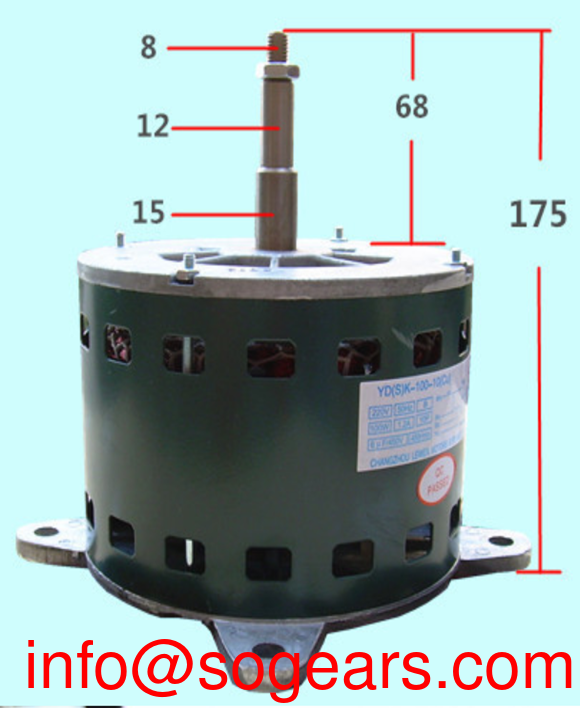
DC motor speed control can be divided into excitation control method and armature voltage control method. Excitation control is used sparingly, and armature voltage control is used in most applications. The application of dc motor speed control system. With the advancement of power electronics technology, changing the armature voltage can be achieved in a variety of ways, among which pulse width modulation (PWM) is a commonly used method of changing the armature voltage. The method is to adjust the armature voltage U of the DC motor by changing the ratio of the on-time of the motor armature voltage to the energization period (ie, the duty ratio), thereby controlling the motor speed.
The application of dc motor speed control system. The triangular wave generator is used to generate a triangular wave UT of a certain frequency, which is added by the adder to the input command signal UI to generate a signal UI UT, which is then sent to the comparator. The comparator is an op amp that operates in an open-loop state with extremely high open-loop gain and limiting switching characteristics. A slight change in the signal difference between the two inputs causes the comparator to output a corresponding switching signal. In general, the comparator negative input is grounded and the signal UI UT is input from the positive terminal. When UI UT > 0, the comparator outputs a positive level of full amplitude; when UI UT0, the comparator outputs a negative level of full amplitude. The application of dc motor speed control system.
The modulation process of the signal waveform by the voltage-pulse width converter is shown in Fig. 2. Due to the limiting characteristics of the comparator, the amplitude of the output signal US does not change, but the pulse width varies with the UI. The frequency of the US is determined by the frequency of the triangular wave.
When the command signal UI=0, the output signal US is a rectangular pulse with equal positive and negative pulse widths. First, the motor logic control signal is issued by the single chip microcomputer, mainly including the motor running direction signal Dir, the motor speed regulating signal PWM and the motor braking signal Brake. Pulse width modulation is then performed by the TL 494, and its output signal drives the H-bridge power circuit to drive the DC motor. The application of dc motor speed control system. The H-bridge is composed of four high-power enhanced FETs, which function to change the steering of the motor and amplify the drive signal.
In the circuit that realizes the PWM control of the motor, the system uses TL494 chip, and its internal circuit is composed of reference voltage generation circuit, oscillation circuit, intermittent period adjustment circuit, two error amplifiers, pulse width modulation comparator and output circuit, etc., TL494 chip Widely used in single-ended forward double-tube, half-bridge, full-bridge switching power supplies. The application of dc motor speed control system. All pulse width modulation circuits are integrated. The chip has a built-in linear sawtooth oscillator with only two external oscillating components (one resistor and one capacitor). Built-in error amplifier. Internally rejects the 5V reference voltage source. The dead time can be adjusted. The built-in power transistor provides 500mA drive capability. Push or pull two output methods.
NER GROUP CO.,LIMITED
Mobile:+86-13053534623
.png) http://www.bonwaygroup.com/
http://www.bonwaygroup.com/.png) https://twitter.com/gearboxmotor
https://twitter.com/gearboxmotor.png) https://www.facebook.com/sogears1993
https://www.facebook.com/sogears1993Viber/Line/Whatsapp/Wechat: 008613053534623
E-mail:
Address: No.5 Wanshoushan Road, Yantai, Shandong Province, China (264006)
