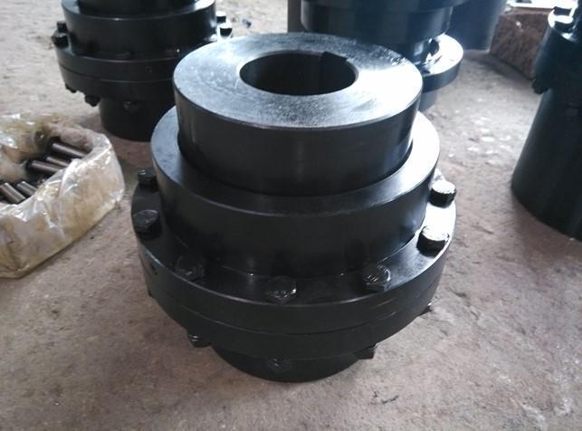
Solid coupling
The Solid coupling coupling is also known as the metal slider coupling. The slider has a circular ring shape and is made of steel or wear-resistant alloy. It is suitable for transmissions with low speed and large torque.
definition:
The solid coupling is also known as the metal cross slider coupling. Its slider is circular and made of steel or wear-resistant alloy. The cross slider coupling is suitable for low speed and large transmission torque. transmission. The solid coupling is composed of two shaft sleeves and a central slider. As a torque-transmitting element, the center slide is usually made of engineering plastics. In special cases, other materials, such as metal materials, can be selected.

composition:
The SL solid coupling is composed of two shaft sleeves and a center slider. The center slider is usually made of engineering plastics as a torque transmission component. In special cases, other materials, such as metal materials, can be selected. The center slider passes The clamping grooves distributed at 90° on both sides are connected with the shaft sleeves on both sides to achieve the purpose of transmitting torque. The center slider and the shaft sleeve are matched with a slight pressure, which can make the coupling in The equipment operates with zero clearance during operation. As the use time increases, the slider may lose its recoil-free function due to wear, but the center slider is not expensive and easy to replace, and it can still play its original role after replacement. Performance.
Slider couplings are often used in general common motors. In some cases, they can also be used to connect servo motors. During use, the relative displacement is corrected by the sliding of the center slider. Because the half coupling and the intermediate disk form a moving pair, it cannot Relative rotation occurs, so the angular velocity of the driving shaft and the driven shaft should be equal. However, when working with relative displacement between the two shafts, the intermediate disk will generate a large centrifugal force, which will increase the dynamic load and wear. So choose It should be noted that the working speed should not be greater than the specified value. This kind of coupling is generally used for speed n<250r/min, the rigidity of the shaft is large, and there is no severe impact.

Structural features:
The material of the coupling parts can be 45 steel, thereby increasing the dynamic load and wear. Therefore, pay attention to the working speed not greater than the specified value when selecting. This kind of coupling is generally used for the speed n<250r/min, the rigidity of the shaft is large, and there is no severe impact.
●The structure of the slider coupling is similar to the cross slider coupling. The difference is that the middle cross slider is a square slider. The middle slider is used to slide in the corresponding radial grooves on the end faces of the half couplings on both sides. In order to realize the coupling of the two halves. This coupling is noisy, low in efficiency, and wears quickly. Generally, it is not used as much as possible. It is only used when the speed is very low. The slider coupling specified in this standard is suitable for oil pump devices or other occasions with small transmission torque. The relative offset of the two axes must be compensated, shock absorption and cushioning performance; its working temperature is -20~70°C. The nominal torque transmitted is 16~500N.m.
●Allowable compensation amount: axial △ x=1~2mm, radial △ y ≤ 0.2mm, angular △α≤ 40'.
characteristic:
The material of the sliding block coupling parts can be 45 steel, and the working surface needs to be heat treated to increase its hardness; Q275 steel can also be used when the requirements are low, without heat treatment. In order to reduce friction and wear, oil should be injected from the oil hole of the middle plate for lubrication during use. Because the half-coupling and the intermediate disc form a moving pair and cannot rotate relative to each other, the angular velocity of the driving shaft and the driven shaft should be equal. However, when working with relative displacement between the two shafts, the middle disk will generate a large centrifugal force, which will increase the dynamic load and wear. Therefore, pay attention to the working speed not greater than the specified value when selecting. This kind of coupling is generally used for the speed n<250r/min, the rigidity of the shaft is large, and there is no severe impact.
The center sliding block and the shaft sleeve are matched with a slight pressure, which enables the coupling to run with zero clearance during the operation of the equipment. As the use time increases, the slider may lose its recoilless function due to wear, but the center slider is not expensive and easy to replace. After replacement, it can still play its original performance. Slider couplings are often used in common motors, and can also be used to connect servo motors on individual occasions. The relative displacement is corrected by the sliding of the center slider during use. Because the resistance to the relative displacement is the friction between the slider and the sleeve, the bearing load between them will not increase due to the increase in the relative displacement.

advantage:
The sliding block coupling can eliminate the additional load between the shafts during the automatic control of the motor. The fixed body adopts splines to slide, and the inner and outer sleeves inside the sliding body can slide relatively in the axial direction; the coupling can Realize the integration of sliding and rotation; in the case of equal turning diameter, the shortest dimension is much smaller than the cross shaft. Improve the uniformity of load distribution on the working surface, can transmit larger torque, but the elasticity is slightly reduced.
application:
Unlike other couplings, the slider coupling does not have an elastic element that can work like a spring, so the bearing load will not increase due to the increase in the relative displacement between the shafts. In any case, this series of couplings are more worthwhile, and the ability to choose sliders of different materials is the biggest advantage of this coupling. Juren can provide a variety of raw material center sliders to suit different applications according to the specific requirements of customers. Generally speaking, one type of material is suitable for zero-clearance, high-torque rigidity and high-torque situations, and the other type of material is suitable for low-precision positioning, without zero-clearance, but has the functions of absorbing vibration and reducing noise. The non-metallic slider also has excellent electrical insulation and can be used as a mechanical fuse. When the engineering plastic slider is damaged, the transmission effect will be completely terminated, so as to protect the valuable mechanical parts. This design is suitable for large parallel relative displacements. The separate three-part design of the slider coupling limits its ability to compensate for axial deviations, for example, it cannot be used in push-pull applications. At the same time, because the center slider is floating, the two-axis movement must ensure that the slider does not fall off.

the difference:
The quincunx elastic coupling ensures that the relative displacement of the two shafts is within the rated allowable range of the coupling. Install the two shaft sleeves on the shaft so that the tenon faces are opposite. Use a wrench to fully tighten the screw on one side of the shaft sleeve to the recommended seating torque. Insert the torx spacer into the fixed shaft sleeve so that the claws can touch the bottom of the groove of the shaft sleeve. Insert the second bushing on the quincunx spacer to ensure that the protruding claw can touch the bottom of the groove of the bushing. It takes a certain amount of force to complete the insertion, which is normal. Ensure the distance between the two shaft sleeves so that the metal of the two shaft sleeves will not directly contact. Fully tighten the screw to its in-place torque to completely fix the second sleeve on the shaft.
The solid coupling ensures that the relative displacement of the two shafts is within the rated allowable value of the coupling. Install the two shaft sleeves on the shaft so that the tenon faces are opposite. Rotate the two shaft sleeves to make the driving tenon with the tenon surface at an angle of 90°, align the groove of the center slider with one of the tenons, and insert the center slider onto the tenon by hand. Put the axial limit washer into the groove bottom of the center slider. Tighten the screws according to the in-place torque to completely fix the two shaft sleeves on the shaft. Take out the gasket to ensure a certain gap between the two shaft sleeves and the center slider to balance the relative axial displacement.
Product Description:
. Excellent high torque rigidity and good vibration absorbability
. No gyration tolerance: Easy to remove
. Great displacement for angular paraller or axial deviation by diaphragm or locking assembly
. Same feature revolving with direction or negative direction
. Iron alloy material
. For high power step motor, servo motor, CNC lathe

select:
Selection of coupling type When selecting a coupling type, the following items should be considered.
①The size and nature of the torque to be transmitted, the requirements for buffering and damping functions, and whether resonance may occur.
②The relative displacement of the axis of the two shafts is caused by manufacturing and assembly errors, shaft load and thermal expansion deformation, and relative movement between components.
③Allowable dimensions and installation methods are the operating space necessary for ease of assembly, adjustment and maintenance. For large couplings, it should be possible to disassemble and assemble without axial movement of the shaft.
In addition, the working environment, service life, lubrication, sealing and economy should also be considered, and then refer to the characteristics of various couplings to select a suitable coupling type.

SL cross WH type solid coupling is also known as metal WH type slider coupling. It consists of two half couplings with radial grooves on the end faces and a middle slider with a tenon at each end. The tenons at both ends of the block are perpendicular to each other, and they are respectively embedded in the grooves of the two half couplings to form a moving pair. If the measuring axis is not concentric or skewed, the slider will slide in the groove during movement, so the concave Lubricant should be added to the working surface of the groove and the sliding block. If the two shafts are not concentric, when the rotation speed is high, the eccentricity of the sliding block will cause great centrifugal wear and additional load to the shaft and the shaft, so it is only applicable It is used in low-speed, high-transmission situations.
The material of the coupling parts can be 45 steel, and the working surface needs to be heat treated to increase its hardness; Q275 steel can also be used when the requirements are lower, without heat treatment. In order to reduce friction and wear, oil should be injected from the oil hole of the middle plate for lubrication during use.

JQ type-jacket coupling
The characteristics of the JQ type-jacket coupling are similar to the sandwich coupling, simple structure, convenient assembly and disassembly, suitable for low-speed (circumferential linear velocity of 5M/S), no impact, and stable vibration load occasions. For the connection of vertical shafts such as agitator.
GJ type clamp shell coupling uses two clamp shells divided along the axial direction, which are clamped by bolts to realize the connection of two shafts. The torque is transmitted by the friction between the two halves of the coupling surface, and the flat key is used as auxiliary Join.
The characteristics of GJL type-vertical clamp coupling are similar to those of clamp coupling, simple structure, easy to assemble and disassemble, suitable for low speed (circumferential speed of 5M/S), no impact, stable vibration load It is suitable for the connection of vertical shafts such as agitators.
WH type-slider coupling has high noise, low efficiency and fast wear. Generally, it is not used as much as possible. It is only used when the speed is very low, such as ball mills.
The material of the SL cross slider coupling parts can be 45 steel, and the working surface needs to be heat treated to improve its hardness; Q275 steel can also be used when the requirements are lower, without heat treatment.

![]()
The best service from our transmission drive expert to your inbox directly.
Our Service
Get in Touch
Yantai Bonway Manufacturer Co.ltd
ANo.160 Changjiang Road, Yantai, Shandong, China(264006)
T+86 535 6330966
W+86 185 63806647