Fluid coupling
Fluid coupling, also known as fluid coupling, is a hydraulic transmission device used to connect a power source (usually an engine or motor) with a working machine, and transmit torque by the change of liquid momentum.
The fluid coupling is a hydraulic transmission device that uses the kinetic energy of the liquid to transfer energy. It uses liquid oil as the working medium, and converts the mechanical energy and the kinetic energy of the liquid to each other through the pump wheel and the turbine, thereby connecting the prime mover and the working machinery Realize the transmission of power. According to its application characteristics, fluid couplings can be divided into three basic types, namely ordinary type, torque-limiting type, speed-regulating type and two derived types: fluid coupling transmission and hydraulic reducer.

working principle:
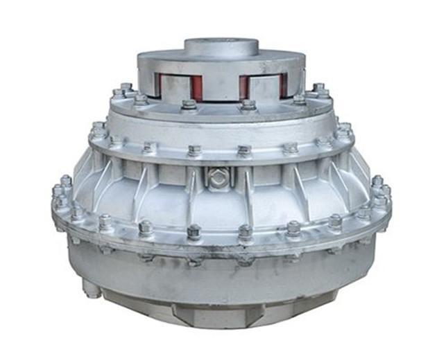
The fluid coupling is a non-rigid coupling with liquid as the working medium. The pump wheel and turbine of the fluid coupling form a closed working chamber that allows the liquid to circulate. The pump wheel is installed on the input shaft, and the turbine is installed on the output shaft. The two wheels are semi-circular rings with many blades arranged in the radial direction. They are arranged oppositely and do not touch each other. There is a gap of 3mm to 4mm between them, and they form an annular working wheel. The driving wheel is called the pump wheel, the driven wheel is called the turbine, and both the pump wheel and the turbine are called the working wheel. After the pump wheel and the turbine are assembled, an annular cavity is formed, which is filled with working oil.
The pump wheel is usually driven by an internal combustion engine or a motor to rotate, and the blades drive the oil. Under the action of centrifugal force, the oil is thrown to the edge of the pump wheel. Since the radius of the pump wheel and the turbine are equal, when the speed of the pump wheel is greater than the turbine speed At this time, the hydraulic pressure at the outer edge of the impeller blades is greater than the hydraulic pressure at the outer edge of the turbine blades. Due to the pressure difference, the liquid impacts the turbine blades. Rotate in the same direction. After the kinetic energy of the oil drops, it flows back to the pump wheel from the edge of the turbine blades, forming a circulation loop, and its flow path is like an annular spiral connected end to end. The fluid coupling relies on the interaction of the liquid with the blades of the pump wheel and the turbine to produce the change of momentum moment to transmit torque. When ignoring the wind loss and other mechanical losses when the impeller rotates, its output (turbine) torque is equal to the input (pump wheel) torque.

classification:
According to different uses, fluid couplings are divided into ordinary fluid couplings, torque-limiting fluid couplings and speed regulating fluid couplings. Among them, the torque-limiting hydraulic coupler is mainly used for start-up protection of the motor reducer and impact protection, position compensation and energy buffering during operation; the speed-regulating hydraulic coupler is mainly used for adjusting the input and output speed ratio, and other functions It is basically the same as the torque-limiting fluid coupling.
According to the number of working cavities, the hydraulic coupler is divided into single working cavity hydraulic coupler, double working cavity hydraulic coupler and multi working cavity hydraulic coupler. According to the different blades, fluid couplings are divided into radial blade fluid couplings, inclined blade fluid couplings and rotary blade fluid couplings.

1. Ordinary hydraulic coupler
Ordinary hydraulic coupler is the simplest kind of hydraulic coupler, it is composed of pump wheel, turbine, shell pulley and other main components. Its working cavity has large volume and high efficiency (maximum efficiency reaches 0.96~0.98), and its transmission torque can reach 6 to 7 times the rated torque. However, due to the large overload coefficient and poor overload protection performance, it is generally used for isolating vibration, slowing down starting shock or as a clutch.
2. Moment-limiting hydraulic coupling
The common torque-limiting hydraulic couplers have three basic structures: static pressure relief type, dynamic pressure relief type and compound relief type. The first two are widely used in construction machinery.
(1) Static pressure relief type hydraulic coupling
The figure below is the structure diagram of the static pressure relief fluid coupling. In order to reduce the overload coefficient of the fluid coupling and improve the overload protection performance, it has a higher torque coefficient and efficiency when the transmission ratio is high. Therefore, the structure is different from the ordinary fluid coupling. Its main feature is the symmetrical arrangement of pump wheels and turbines, as well as baffles and side auxiliary chambers. The baffle is installed at the outlet of the turbine, and plays a role of diversion and throttling. This fluid coupling works under partially filled conditions. With this kind of fluid coupling, when the transmission ratio is high, the side auxiliary cavity has very little oil, so the transmission torque is large; and when the transmission ratio is low, the side auxiliary cavity has more oil, which makes the characteristic curve relatively flat and can be compared. Meet the requirements of working machinery well. But it should be pointed out that because the auxiliary cavity of the liquid inlet and outlet side follows the load change and the reaction speed is slow, it is not suitable for working machinery with sudden load changes and frequent starting and braking. Because this type of fluid coupling is mostly used in the transmission of vehicles, it is also called a traction fluid coupling.
(2) Dynamic pressure relief type hydraulic coupling
The dynamic pressure relief type hydraulic coupling can overcome the shortcomings of the static pressure relief type hydraulic coupling that it is difficult to play an overload protection function when suddenly overloaded. The input shaft sleeve is connected with the pump wheel through the elastic coupling and the rear auxiliary cavity shell. The turbine output shaft sleeve is connected with the reducer or working machine, and the fusible plug plays a role of overheating protection. The hydraulic coupler has a front auxiliary cavity and a rear auxiliary cavity. The front auxiliary cavity is a bladeless cavity at the center of the pump wheel and the turbine; the rear auxiliary cavity is composed of the outer wall of the pump wheel and the rear auxiliary cavity shell. The front and rear auxiliary chambers are connected with small holes, the rear auxiliary chamber has small holes connected with the pump wheel, and the front and rear auxiliary chambers rotate together with the pump wheel.
Another function of the rear auxiliary cavity is "extended charge", which can improve the startability. When the engine starts (the turbine has not yet turned), the liquid in the working cavity presents a large circulation, so that the liquid fills the front auxiliary cavity and then passes through the small The hole f enters the rear auxiliary cavity. Because the working chamber is filled with little liquid and the torque is very small, the engine can be started at light load. As the engine speed (that is, the speed of the pump wheel) increases, the liquid in the rear auxiliary cavity will enter the working cavity along the small hole due to the increase in the pressure of the oil ring formed, and the filling volume of the working cavity will increase. Extension". Due to the delayed filling action, the turbine torque increases. After the torque reaches the starting torque, the turbine starts to rotate.

3. Speed-regulating hydraulic coupling
The variable speed hydraulic coupler is mainly composed of pump wheel, turbine, scoop tube chamber, etc., as shown in the figure below. When the driving shaft drives the pump wheel to rotate, under the combined action of the blades and the cavity in the pump wheel, the working oil will gain energy and be sent to the outer circumference of the pump wheel under the action of inertial centrifugal force to form a high-speed oil flow. The high-speed oil flow on the outer circumference side of the wheel is combined with the radial relative speed and the circumferential speed of the pump wheel outlet, and rushes into the inlet radial flow channel of the turbine, and passes the oil flow moment along the radial flow channel of the turbine. The change pushes the turbine to rotate, and the oil flows to the turbine outlet at its radial relative velocity and the circumferential velocity at the turbine outlet to form a combined velocity, flows into the radial flow channel of the pump wheel, and regains energy in the pump wheel. Such repeated repetitions form a circulating flow circle of working oil in the pump wheel and turbine. It can be seen that the pump wheel converts the input mechanical work into oil kinetic energy, and the turbine converts the oil kinetic energy into output mechanical work, thereby realizing power transmission.

Advantages and disadvantages:
advantage:
(1) It has the function of flexible transmission and automatic adaptation.
(2) It has the functions of reducing shock and isolating torsional vibration.
(3) It has the function of improving the starting ability of the power machine and making it start with load or no load.
(4) It has an overload protection function to protect the motor and working machine from damage when the external load is overloaded.
(5) It has the functions of coordinating the sequential start of multiple power engines, balancing the load and smoothly paralleling.
(6) With flexible braking and deceleration function (refers to hydraulic retarder and locked-rotor damping hydraulic coupling).
(7) With the function of delaying the slow start of the working machine, it can start the large inertia machine smoothly.
(8) It has strong adaptability to the environment and can work in cold, humid, dusty, and explosion-proof environments.
(9) Cheap cage motors can be used to replace expensive winding motors.
(10) No pollution to the environment.
(11) The transmission power is proportional to the square of the input speed. When the input speed is high, the energy capacity is large and the cost performance is high.
(12) With the function of stepless speed regulation, the speed-regulating hydraulic coupler can change the output torque and output speed by adjusting the liquid filling amount of the working chamber during operation under the condition that the input speed is unchanged.
(13) With clutch function, speed-regulating and clutch-type fluid couplings can start or brake the working machine without stopping the motor.
(14) It has the function of expanding the stable operation range of the power machine.
(15) It has the power-saving effect, which can reduce the starting current and duration of the motor, reduce the impact on the grid, reduce the installed capacity of the motor, and the large inertia is difficult to start. The torque-limiting hydraulic coupler and the centrifugal mechanical application speed regulation The energy-saving effect of hydraulic coupling is remarkable.
(16) There is no direct mechanical friction except for bearings and oil seals, with low failure rate and long service life.
(17) Simple structure, easy operation and maintenance, no need for particularly complicated technology, and low maintenance cost.
(18) High performance-to-price ratio, low price, low initial investment and short payback period.

Disadvantages:
(1) There is always slip rate and slip power loss. The rated efficiency of the torque-limiting fluid coupling is approximately equal to 0.96, and the relative operating efficiency of the speed-regulating fluid coupling and centrifugal machinery matching is between 0.85 and 0.97 .
(2) The output speed is always lower than the input speed, and the output speed cannot be as accurate as gear transmission.
(3) The speed-regulating hydraulic coupling requires an additional cooling system, which increases investment and operating costs.
(4) It occupies a large area and needs a certain space between the power machine and the working machine.
(5) The speed control range is relatively narrow, the speed control range matching with centrifugal machinery is 1~1/5, and the speed control range matching with constant torque machinery is 1~1/3.
(6) No torque conversion function.
(7) The ability to transmit power is proportional to the square of its input speed. When the input speed is too low, the coupler specifications increase and the performance-price ratio decreases.

Application areas:
car
The fluid coupling was used in early semi-automatic transmissions and automatic transmissions of automobiles. The pump wheel of the fluid coupling is connected with the flywheel of the engine, and the power is transmitted from the engine crankshaft. In some cases, the coupler is strictly a part of the flywheel. In this case, the hydrodynamic coupling is also called a hydrodynamic flywheel. The turbine is connected to the input shaft of the transmission. The liquid circulates between the pump wheel and the turbine, so that torque is transmitted from the engine to the transmission, driving the vehicle forward. In this regard, the role of the fluid coupling is very similar to the mechanical clutch in a manual transmission. Because the hydraulic coupler cannot change the torque, it has been replaced by a hydraulic torque converter.
Heavy industry
It can be used in metallurgical equipment, mining machinery, power equipment, chemical industry and various engineering machinery.

Features:
The fluid coupling is a flexible transmission device. Compared with the ordinary mechanical transmission device, it has many unique features: it can eliminate shock and vibration; the output speed is lower than the input speed, and the speed difference between the two shafts increases with the load Increase; overload protection performance and starting performance are good, the input shaft can still rotate when the load is too large, and will not cause damage to the power machine; when the load is reduced, the output shaft speed increases until it is close to the input shaft speed, so that the transmission torque Tends to zero. The transmission efficiency of the fluid coupling is equal to the ratio of the output shaft speed to the input shaft speed. Generally, the high efficiency can be obtained when the rotational speed ratio of the normal working condition of the fluid coupling is above 0.95. The characteristics of the fluid coupling are different due to the different shapes of the working chamber, the pump wheel and the turbine. It generally relies on the shell to dissipate heat naturally and does not require an oil supply system for external cooling. If the oil of the fluid coupling is emptied, the coupling is in a disengaged state and can act as a clutch. However, the fluid coupling also has disadvantages such as low efficiency and narrow efficiency range.
![]()
The best service from our transmission drive expert to your inbox directly.
Our Service
Get in Touch
Yantai Bonway Manufacturer Co.ltd
ANo.160 Changjiang Road, Yantai, Shandong, China(264006)
T+86 535 6330966
W+86 185 63806647