Speed increaser gearbox
Hollow shaft planetary gearbox, hollow shaft gearbox, hollow shaft bevel gearbox, right angle gearbox hollow shaft, gearbox shaft design, dual shaft gearbox, gearbox shaft material, through shaft gearbox
Our company has recently completed a major project on wind turbines. We provide our customers with major gearboxes and generators. This prompted our customers' projects to be completed smoothly. The customer response is very good.
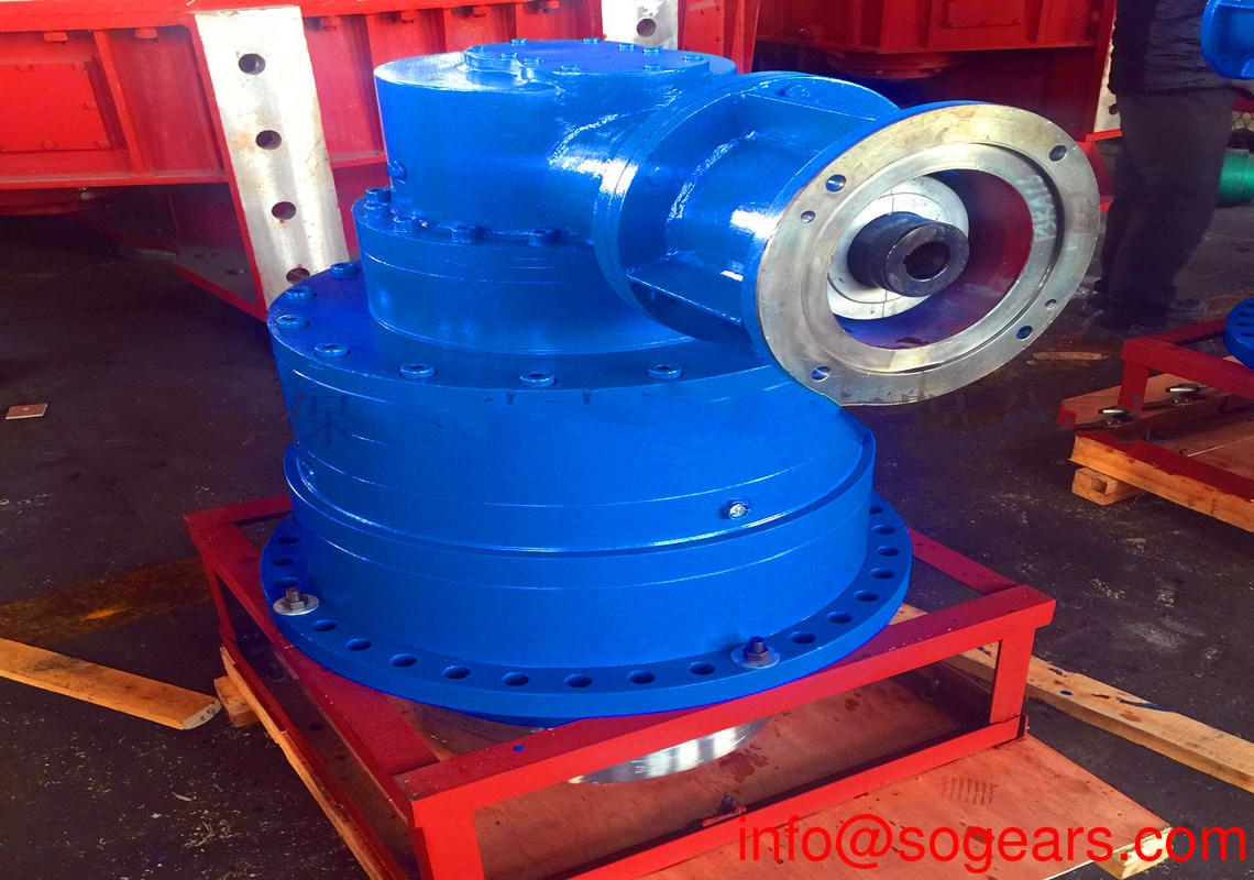
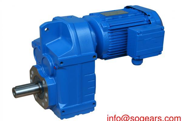
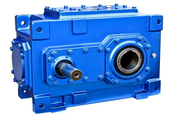
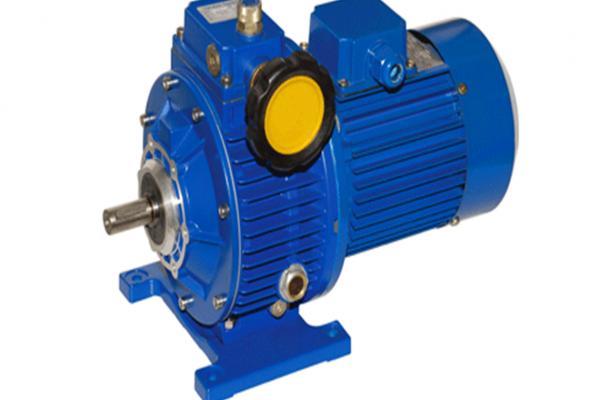
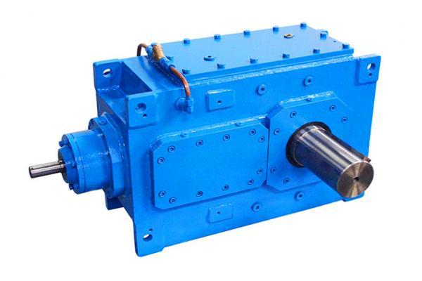
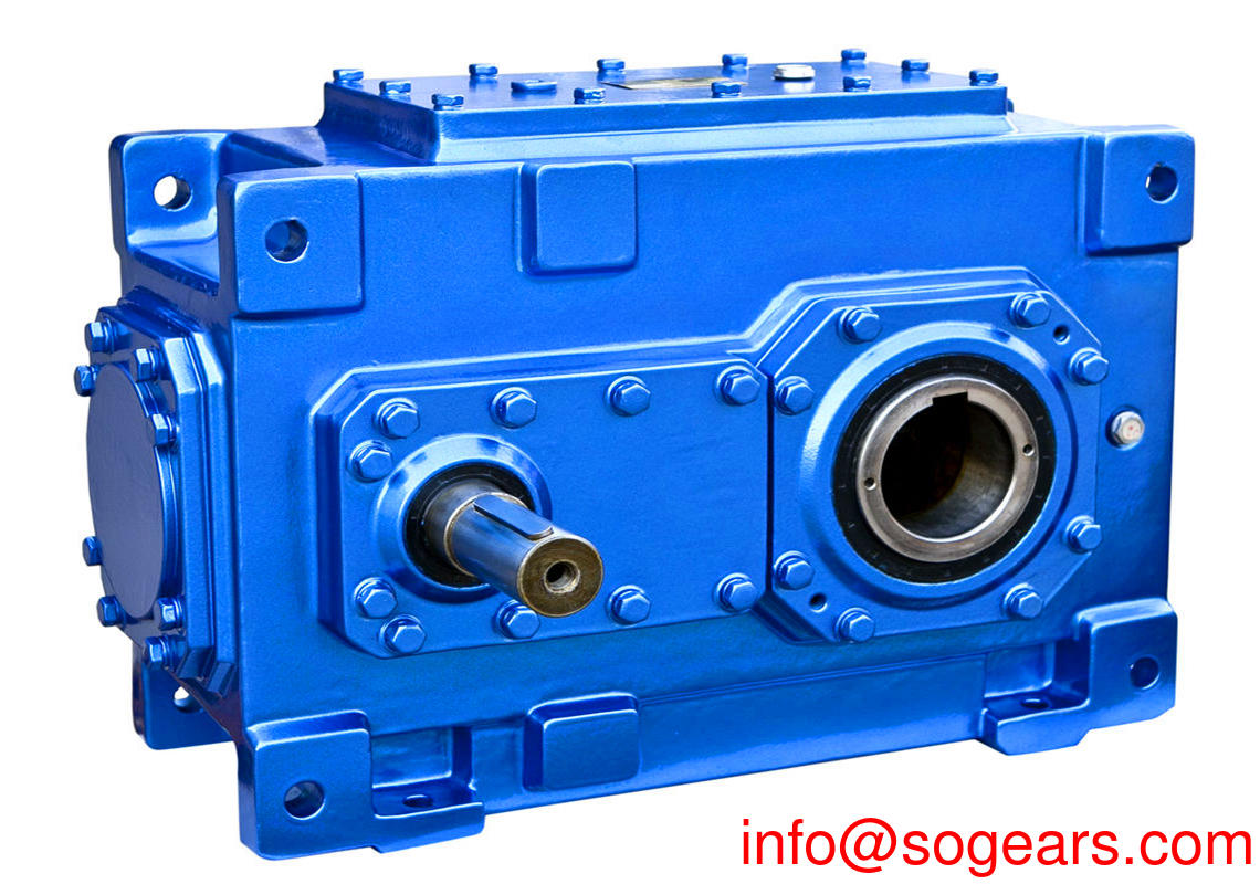
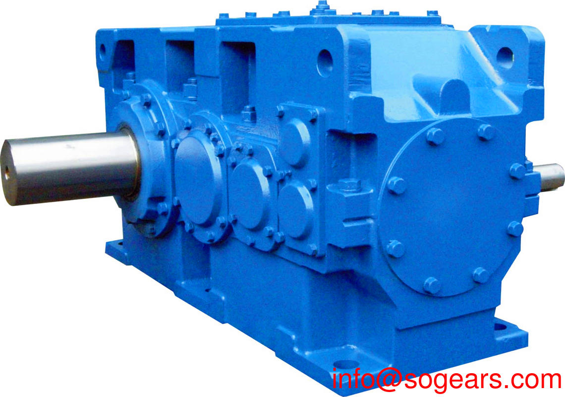
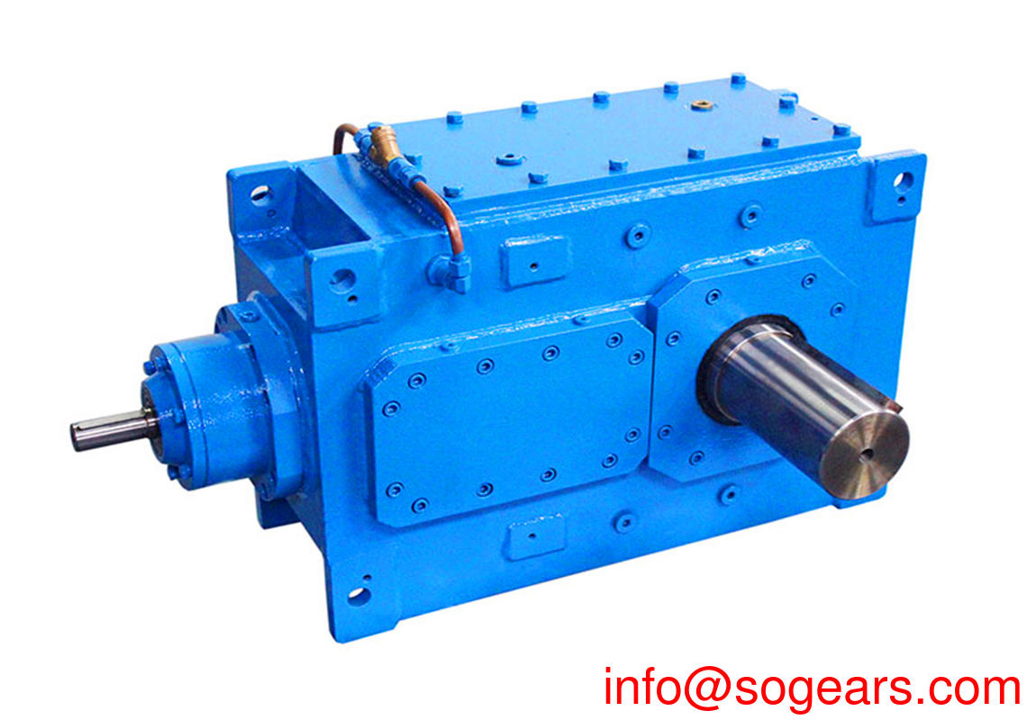
Hollow shaft planetary gearbox Ratio up to i=2900 Torque from 770 Nm up to 135.000 Nm Output: Hollow shaft for scrink disc or spline, shaft with key or with spline. We make the High Precision Hollow shaft planetary gearbox or with a High Precision Spiral Bevel speed increaser gearbox in Hollow Shaft speed increaser gearbox. Input shaft diameter: From12 to 34mm dependi and Hollow shaft planetary gearbox size: 17 gearbox sizes available, Output shaft diameter: From 11to 75mm more kinds. The Sogears Harmonic Hollow shaft planetary gearbox delivers High-Torque and High-Accuracy with a Hollow Shaft design. The gearhead incorporates continuous backlash, Flange-, foot- and hollow shaft-mounted versions, or combinations of these mounting options are available. These gearboxes are of a modular design. Its transmission components such as couplings (hollow shaft gearhead). Oriental are all processing with a strong test and The torque applied to each gear in the planetary gear mechanism is shown. For high torques at mean speeds: Our Hollow shaft planetary gearbox of the P series, Whether hollow shaft or solid shaft, with a key, smooth or spline according to DIN standard.


The working principle of the well-known wind power generation is relatively simple. The wind wheel rotates under the action of the wind. It converts the kinetic energy of the wind into the mechanical energy of the wind turbine shaft, and the generator rotates to generate electricity under the driving of the wind turbine shaft. Broadly speaking, wind energy is also solar energy, so it can also be said that wind turbines are thermal energy generators that use the sun as a heat source and the atmosphere as a working medium.
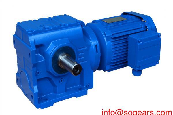
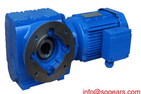
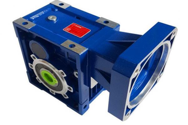
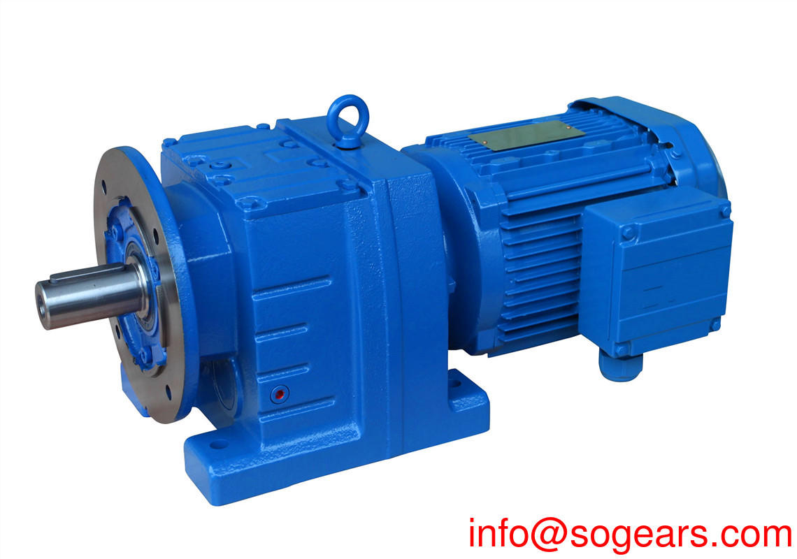
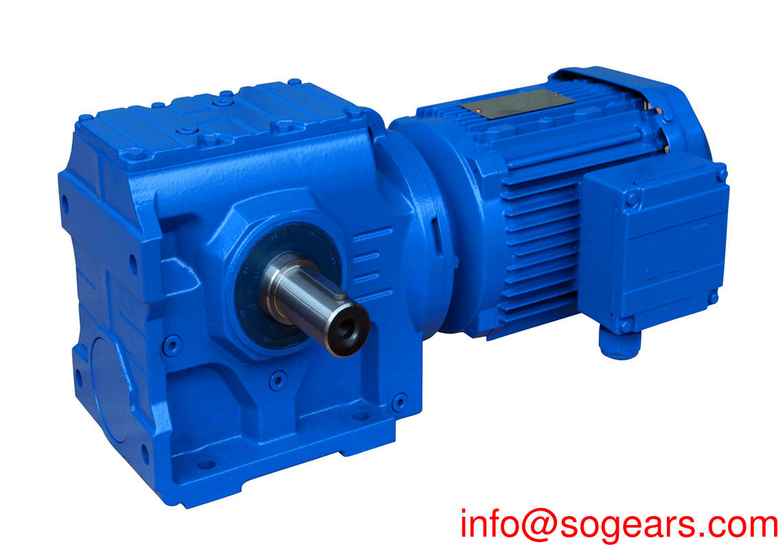
With a ground and case hardened spiral bevel gearing allows for dual shaft and hollow shaft right angle outputs, Our Hollow shaft planetary gearbox allows you to directly power a machine shaft via a clamping, not only for the planetary gearbox and the right-angle gearbox with hollow shaft, but the inline shaft type. It is very compatible to all kinds of electric motors; High Output Torque and Low noise; Diverse combination with Planetary Gearboxes; √ Hollow Shaft √ Backlash 14~18.
We are from China, manufacturing the Hollow Shaft Planetary Gearbox with Input Adapter, Find details about China sogears Gearbox, speed increaser gearbox from Hollow Shaft Planetary Gearbox with Input Adapter, email us or call us, we will send you the best quotation. Our low-backlash economy planetary gearboxes offer high output or torque throughput, As a further option we offer the hollow shaft EPL, A new style Precision Hollow Shaft Planetary Gear from Harmonic Drive, and distributed by Electromate, was designed based on the popular.


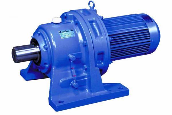
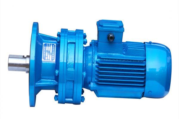
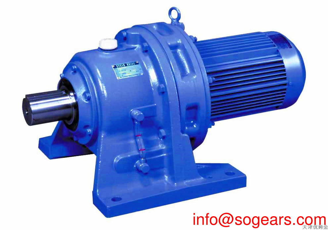
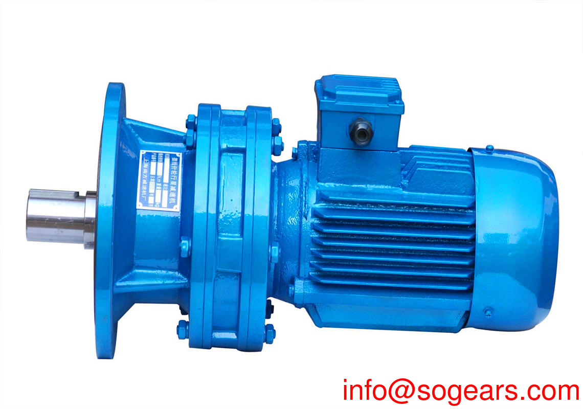
Planetary speed increaser gearbox is a versatile industrial product which can reduce the speed of the motor and increase the output torque.Planetary speed increaser gearbox can be used as supporting parts for lifting, mining, transportation, construction and other industries.
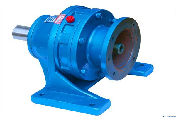
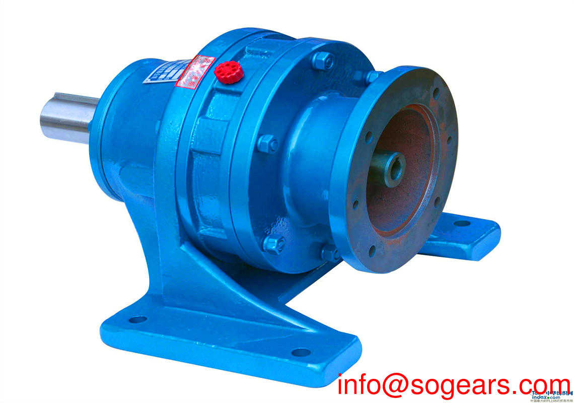
Series: number of sets of planetary gears.Since one set of planetary gears cannot meet the requirements of a larger transmission ratio, sometimes two or three sets are needed to meet the requirements of a larger transmission ratio of the user. As the number of planetary gears is increased, the length of the second or third stage speed increaser gearbox will be increased and the efficiency will be decreased.Return clearance: when the output end is fixed and the input end is rotated clockwise and counterclockwise to produce rated torque +-2% at the input end, there is a tiny angular displacement at the input end of speed increaser gearbox.With the continuous development of speed increaser gearbox industry, more and more companies use the speed increaser gearbox, planetary speed increaser gearbox is a kind of industrial products, planetary speed increaser gearbox is a kind of conveying mechanism and its structure by a combined closely with the inner gear ring on the Speed increaser gearboxes shell, ring gear center has a sun gear of external power driven between a group of bisected by three gear combinations on the tray of the planetary gear set, this group of planetary gear on the output shaft, and the sun on the annular gear tooth support during the planktonic in;When the input side power drives the solar tooth, it can drive the planetary gear to rotate, and follow the track of the inner gear ring to revolution along the center. The rotation of the planet drives the output power of the output shaft connected to the tray.A gear speed converter is used to reduce the rotation number of the motor (motor) to the desired rotation number and to obtain a higher torque mechanism.In the speed increaser gearbox mechanism used for transmission of power and motion, the planetary speed increaser gearbox belongs to the precision type, the reduction ratio can be accurate to 0.1-0.5 RPM.

An inner gear ring (A) is closely connected to the Speed increaser gearboxes shell. At the center of the ring tooth is A solar gear driven by external force (B). Between the two, there is A set of planetary gear set (C) which is equally assembled on the tray by three gears.When the input side power drives the solar gear, it can drive the planetary gear to rotate, and follow the track of the inner gear ring to revolve around the center. The rotation of the star drives the output power of the output shaft connected to the tray.
The well-known wind power generation is an electrical device that converts wind energy into mechanical energy and mechanical energy into electrical energy. Broadly speaking, it is a thermal energy utilization engine that uses the sun as a heat source and the atmosphere as a working medium. Wind power uses natural energy. It is much better than diesel power generation. However, if it is used in an emergency, it is still not as good as a diesel generator. Wind power cannot be considered as a backup power source, but it can be used for a long time.
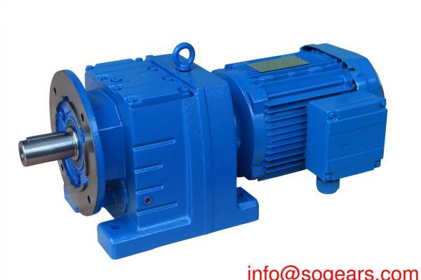
Sogears brand Planetary speed increaser gearbox with hollow-shaft, a higher torque gear units are the ideal choice for applications, either fixed industrial, using the Geared motors for any application with a wide range of Speed increaser gearboxes, low cost planetary,dimensions and where high torque, hollow shaft and low cost is a necessity. When you need an honest hard working Hollow shaft planetary gearbox think of ours and we will give you our warrante
The principle of the well-known wind power generation is to use the wind to drive the rotation of the windmill blades, and then increase the speed of the rotation through the speed increaser to promote the generator to generate electricity. According to the current wind turbine technology, about three meters per second of the breeze speed (the degree of breeze), you can start generating electricity.
It also could be with a High-class synchronous servo motor with integrated Hollow shaft planetary gearbox. Exceptionally large flange hollow shaft for passing through media. Super compact , hollow shaft gearboxes offer shaft mount designs with keyways, square splines, involute splines, or smooth bores with shrink disks.


The weight of the planetary gear transmission device is generally proportional to the weight of the gear, and the weight of the gear has a great relationship with the material and heat treatment hardness.For example, at the same power, the weight of the carburized hardened gear will be about 1/3 of the weight of the tempered gear.Therefore, according to the structural characteristics of planetary speed increaser gearbox and the load nature of gears, hardtooth surface gears should be widely used.There are many heat treatment methods to obtain gear with hard tooth surface, such as surface quenching, overall quenching, carburizing quenching, nitriding, etc., which should be selected according to the characteristics of planetary speed increaser gearbox.
1. Surface hardening
Common surface quenching methods are high-frequency quenching (for small gears) and flame quenching (for large gears).The surface hardened layer works best when it includes the base of the tooth root.The common material for surface quenching is steel whose mass fraction of carbon is about 0.35%~0.5%. The hardness of tooth surface can reach 45~55HRC.
2. Carburizing and quenching
Carburizing and quenching gear has the maximum bearing capacity, but the finishing process (gear grinding) must be used to eliminate heat treatment deformation to ensure the accuracy.
Carburizing hardened gears are usually made of alloy steel with a mass fraction of 0.2%~0.3% before carburizing, and the tooth surface hardness is usually within the range of 58~62HRC.When it is lower than 57HRC, the strength of tooth surface decreases significantly, while when it is higher than 62HRC, brittleness increases.The hardness of tooth center is generally 310~330HBW.The hardness of the carburized hardened gear should be gradually decreased from the surface of the gear tooth to the deep layer, while the effective carburizing depth should be gradually decreased from the surface to the deep layer, while the effective carburizing depth should be the depth from the surface to the hardness of 52.5HRC.
The effect of carburizing and quenching on the bending fatigue strength of the gear tooth is not only to increase the hardness of the core, but also to reduce the stress of the maximum tensile stress zone of the gear tooth.Therefore, when grinding teeth can not grind the root of the teeth, hobbing to use the amount of grinding hob.
3, nitriding
The adoption of nitriding can ensure the tooth surface hardness and wear resistance of the gear with minimum deformation, and the final finishing can no longer be carried out after heat treatment to improve the bearing capacity.This has special significance for the inner gear which is not easy to grind teeth.
4. Hardness combination of meshing gears
When the gear surface is soft, the hardness of the gear surface should be higher than that of the gear.When both wheels have hard tooth surface and high hardness, the hardness of the two wheels is the same.

Selecting good material of planetary speed increaser gearbox is beneficial to improve the bearing capacity and service life of speed increaser gearbox.
In speed increaser gearbox family, the planetary speed increaser gearbox with its small size, high transmission efficiency, wide reduction range, high precision many advantages, and is widely used in servo, stepping, dc and other transmission systems.Its function is in the premise of ensuring precision transmission, mainly used to reduce the rotation speed and increase torque and reduce the load/motor rotational inertia ratio.In the past few years, some users in the use of speed increaser gearbox, due to illegal installation and other human factors, and lead to the speed increaser gearbox output shaft broken, so that the enterprise suffered unnecessary losses.Therefore, in order to better help the majority of users with good speed increaser gearbox, to you in detail how to install the correct planetary speed increaser gearbox.
Correct installation, use and maintenance of speed increaser gearbox is an important link to ensure the normal operation of mechanical equipment.Therefore, when installing the planetary speed increaser gearbox, please be sure to strictly follow the following installation and use of related matters, carefully assemble and use.

The first step
Before installation, confirm whether the motor and speed increaser gearbox are intact, and strictly check whether the size of each part connected with the motor and speed increaser gearbox matches. Here are the size and matching tolerance of the positioning boss, input shaft and speed increaser gearbox groove of the motor.
The second step
Unscrew the screw on the outer dustproof hole of speed increaser gearbox flange, adjust the clamping ring of PCS system to align the side hole with the dustproof hole, insert the inner hexagon to tighten.After that, remove the motor shaft keys.
The third step
Connect the motor to speed increaser gearbox naturally.The concentricity of the output shaft of speed increaser gearbox and the input shaft of the motor must be consistent when connected, and the outer flange of the two must be parallel.If the concentricity is not consistent, the motor shaft will be broken or speed increaser gearbox gear wear.
In addition, in the installation, do not use hammer and other blows, prevent the axial force or radial force too much damage to the bearing or gear.Be sure to tighten the mounting bolt before tightening the force bolt.Before installation, wipe away the anti-rust oil of motor input shaft, positioning boss and connecting part of speed increaser gearbox with gasoline or zinc-sodium water.Its purpose is to ensure tight connection and flexibility of operation, and prevent unnecessary wear and tear.

Before the motor and speed increaser gearbox are connected, the motor shaft keyway should be perpendicular to the tightening bolt.To ensure a uniform force, first screw the installation bolts at any diagonal position, but do not screw tight, then screw the installation bolts at the other two diagonal positions, and finally screw the four installation bolts one by one.Finally, tighten the force bolt.All tightening bolts shall be fixed and checked by the torque plate hand according to the indicated torque data.
Correct installation between speed increaser gearbox and mechanical equipment is the same as correct installation between speed increaser gearbox and drive motor.The key is to ensure that the output shaft of speed increaser gearbox and the drive part of the shaft concentricity.
Lubrication maintenance editor
Load the recommended type and value of grease into the planetary speed increaser gearbox.The planetary speed increaser gearbox is lubricated with lubricating oil.For vertically mounted planetary speed increaser gearboxs, additional lubrication measures are used since the lubricant may not guarantee reliable lubrication of the topmost bearing.
Prior to operation, fill the planetary speed increaser gearbox with an appropriate amount of lubricating oil. The viscosity of the lubricating oil is selected according to the following list.The planetary speed increaser gearbox is usually equipped with an oil hole and a drain plug.Therefore, when ordering planetary speed increaser gearbox must specify the installation location.

Reasons for editing
1. The pressure in the oil tank rises
In closed speed increaser gearbox, each pair of gears meshing friction will send out quantity of heat, according to the Boyle trails by specific law, as the lengthen of time running, to gradually rise, slow down the temperature inside the case and the reduction volume inside the case, so the pressure increase, in the cabinet in the lubricating oil splash, sprinkled on the inner wall of the deceleration box.Because the oil is relatively permeable, under the pressure of the box, where the seal is not tight, oil will leak from where.
2. Unreasonable structure design of speed increaser gearbox causes oil leakage
If the designed speed increaser gearbox does not have a ventilation hood, speed increaser gearbox cannot achieve pressure equalization, resulting in higher and higher pressure in the box and oil leakage.
3, too much refueling
speed increaser gearbox in the process of operation, the oil pool is stirred very badly, lubricating oil in the machine everywhere splash, if too much, so that a lot of lubricating oil accumulation in the shaft seal, joint surface, resulting in leakage.
4. Improper maintenance process
In the maintenance of the equipment, due to the combination of surface dirt removal is not complete, or the choice of sealant is improper, the direction of the sealing parts installed in the opposite direction, not timely replacement of the sealing parts will also cause oil leakage.


- Basic structure: Hollow shaft planetary gearbox, shaft, female splines, hollow shaft with shrink disc, hexagonal shaft; Input version for: electric motor.
- Cabin: The cabin contains key equipment forthe well-known wind power generation, including gearboxes and generators. Maintenance personnel can enter the cabin through the wind turbine tower. At the left end of the nacelle are wind turbine rotors, ie rotor blades and shafts.
- Rotor blades: catch wind and transmit wind power to the rotor shaft. On modern 600 kW wind turbines, each rotor blade has a measured length of approximately 20 meters and is designed to resemble an airplane's wing.
- Axis: The rotor axis is attached to the low speed shaft of the wind turbine.
- Low speed shaft: The low speed shaft of the wind turbine connects the rotor shaft to the gearbox. On modern 600 kW wind turbines, the rotor speed is quite slow, about 19 to 30 revolutions per minute. There are conduits for the hydraulic system in the shaft to activate the operation of the aerodynamic brake.
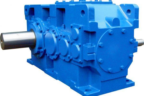
- Gearbox: The left side of the gearbox is the low speed shaft, which increases the speed of the high speed shaft to 50 times the low speed shaft.
- High-speed shaft and its mechanical brake: The high-speed shaft runs at 1500 rpm and drives the generator. It is equipped with an emergency mechanical brake for when the aerodynamic brake fails or when the wind turbine is being serviced.
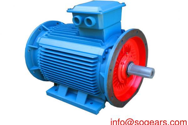
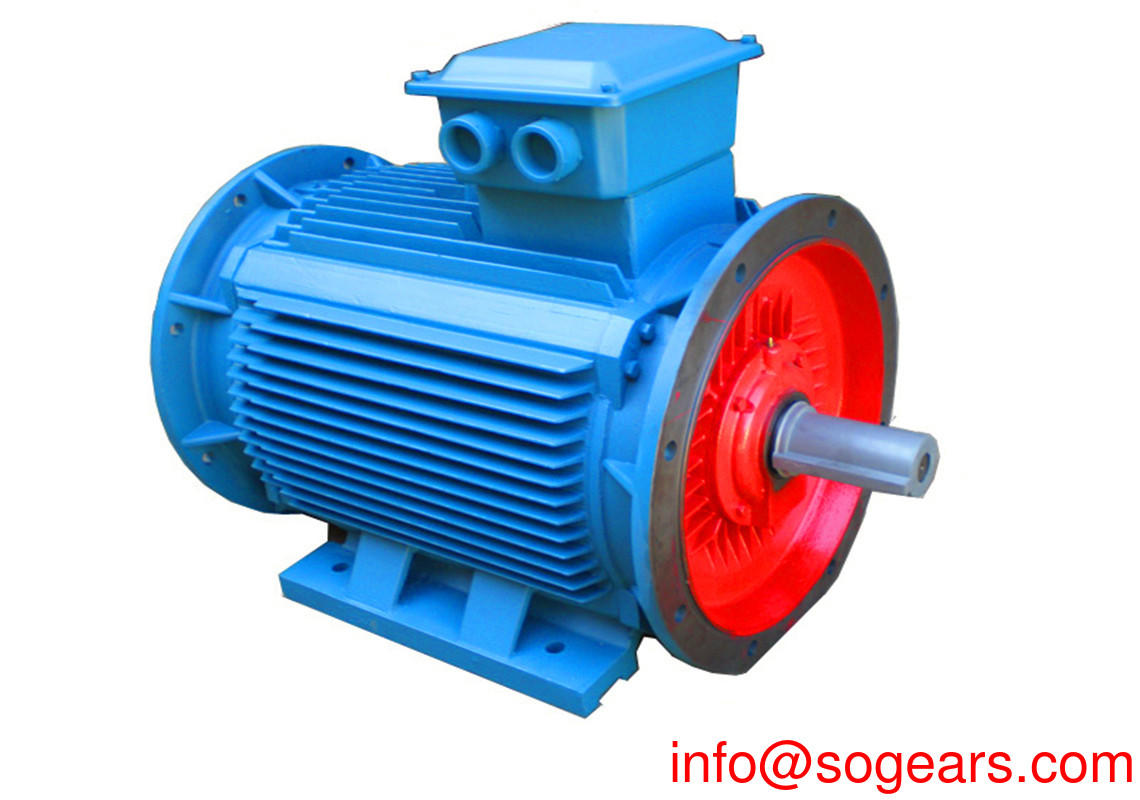
- Generator: Usually called induction motor or asynchronous generator. On modern wind turbines, the maximum power output is typically between 500 and 1500 kW.
- Yaw device: Rotate the nacelle with the motor so that the rotor is facing the wind. The yaw device is operated by an electronic controller that can sense the wind direction through the wind vane. Usually, when the wind changes its direction, the wind turbine will only deflect a few degrees at a time.

- Electronic controller: Contains a computer that continuously monitors the state of the wind turbine and controls the yaw device. To prevent any malfunction (ie overheating of the gearbox or generator), the controller can automatically stop the rotation of the wind turbine and call the wind turbine operator via a telephone modem.
- Hydraulic system: An aerodynamic brake used to reset a wind turbine.
- Cooling element: Contains a fan for cooling the generator. In addition, it contains an oil cooling element for cooling the oil in the gearbox. Some wind turbines have water cooled generators.
- Tower: The wind turbine tower carries the nacelle and rotor. Usually tall towers have an advantage because the higher the ground, the greater the wind speed. Modern 600 kW wind turbines have tower heights of 40 to 60 meters. It can be a tubular tower or a lattice tower. Tubular towers are safer for maintenance personnel as they can reach the top of the tower through an internal ladder. The advantage of a latticed tower is that it is relatively inexpensive.
- Anemometer and wind vane: used to measure wind speed and direction
- Tail rudder: A small wind turbine (usually 10 kW or less) that is common in wind direction on a horizontal axis. Located behind the rotor, it is connected to the rotor. The main function is to adjust the fan steering so that the fan is facing the wind direction. The second function is to make the wind turbine head deviate from the wind direction in the case of windy wind conditions, so as to reduce the speed and protect the fan.

![]()
The best service from our transmission drive expert to your inbox directly.
Our Service
Get in Touch
Yantai Bonway Manufacturer Co.ltd
ANo.160 Changjiang Road, Yantai, Shandong, China(264006)
T+86 535 6330966
W+86 185 63806647