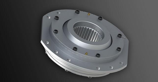
Splined coupling
The characteristics of the DC series drum gear coupling for reel are: can transmit large torque, large radial load capacity, can compensate axis deviation, can be applied to ordinary shaft extension reducer, compact structure, assembly and folding adjustment Convenient, with wear indicator, stable and reliable, especially suitable for lifting mechanism of lifting equipment. The Splined coupling for the drum is a flexible coupling, which is mainly used for the connection between the output shaft of the reducer of the lifting mechanism in the lifting equipment and the wire rope drum. It is also suitable for other similar transmission and rotation Mechanical equipment that bears radial load, but cannot be used as a transmission that needs to bear axial load.

Basic parameters and main dimensions of couplings for DC series reels
Splined coupling
The basic parameters and main dimensions of the DC series reel coupling
Model Permissible Speed Nominal Torque Radial Load Shaft Hole External Dimensions Reel Coupling Dimensions Wear Scale Axial Clearance Load Position Moment of Inertia Mass
Diameter length
nmax Tmax Frmax dmax(H7) Lmin D D1(h6) D2(h9) L1 L2 L3 L4 L5 L6 S(h9) Ф2 n-d2 bolt a d3 r m1 Xmax e I m
r/min N.m N mm mm mm mm Kg.㎡ Kg
DC01A
DC01B 200 16000 18000 110 185 400 280 180 80 85 15
20 25 26 11 360 360 10-18 M16 30 M16 2.5 1.0 ±2.5 88 1.0 80
DC02A
DC02B 200 22400 25000 125 200 420 310 212 80 95 15
20 25 26 11 380 380 10-18 M16 30 M16 2.5 1.0 ±2.5 88 1.5 100
DC03A
DC03B 200 31500 35500 150 225 450 340 230 80 105 20 25 34 11 400 400 10-22 M20 30 M20 2.5 1.0 ±2.5 88 2.5 120
DC35*
DC35B 200 45000 50000 160 235 510 400 250 95 115 20
25 30 34 15 460 460 10-22 M20 30 M20 2.5 1.4 ±2.5 106 3.0 150
DC04A
DC04B 200 63000 71000 200 250 550 420 280 95 130 20
25 30 34 15 500 500 14-22 M20 20 M20 2.5 1.4 ±2.5 106 4.5 190
DC05*
DC05B 200 90000 90000 220 265 580 450 215 95 145 20
25 30 34 15 530 530 14-22 M20 20 M20 2.5 1.4 ±2.5 110 7.25 245
DC55*
DC55B 200 125000 112000 240 290 620 500 345 101 160 25
30 35 35 19 560 560 20-22 M20 13.3 M20 2.5 1.8 ±2.5 110 10.3 330
DC06A
DC06B 200 160000 140000 260 300 650 530 375 101 170 25
30 35 35 19 580 600 20-22 M20 13.3 M20 2.5 1.8 ±2.5 116 15.5 385
DC65*
DC65B 200 190000 165000 270 300 665 545 387 101 175 25
30 35 35 19 590 615 26-22 M20 10 M20 4 1.8 ±2.5 116 18.3 435
DC07A
DC07B 200 224000 180000 280 310 680 560 400 101 180 25
30 35 35 19 600 630 26-22 M20 10 M20 4 1.8 ±2.5 116 21.4 485
DC08A
DC08B 200 315000 224000 300 345 720 600 437 111 185 35 43 35 21 640 660 26-26 M24 10 M24 4 2.2 ± 2.5 118 30.6 550
DC09A
DC09B 200 450000 280000 340 380 780 670 487 111 200 35 43 35 21 700 730 26-26 M24 10 M24 4 2.2 ±2.5 118 40.2 650
DC10A
DC10B 200 560000 355000 380 420 850 730 545 111 215 35 43 35 21 760 800 26-26 M24 10 M24 4 2.2 ±2.5 120 65.1 890
Selection method and calculation
1. The selection of drum-shaped gear couplings for the reel is generally based on the actual working conditions of the lifting equipment, the shaft extension of the reducer and the connection size of the reel.
2. The selection of the coupling can be calculated according to the calculated torque and the super radial load: Tk≤Tkmax max kmax
In the formula: the calculated torque at the Tk connection is given by the following formula:
Tk=9550NT/nT.ηT.k2.
Tkmax---allowable torque of standard coupling N.m
Fr--The radial load actually borne by the joint N
Fmax-allowable extra large radial load of standard coupling N
NT--The output power of the reducer, or the winding power of the wire rope drum Kw
nT--reel speed r/min in stable operation
ηT-the power of the drum support bearing ηT = 0.98 rolling bearing,
ηT=0.96 rolling bearing,
k1--radial load compensation coefficient (given in Table 3)
k2-working level coefficient (given by table 4)
Φ6--dynamic load factor is given by the following formula
Φ6=(1+Φ2)/2
Φ2--lifting load factor, generally between 1-2
Table 3 Radial load compensation coefficient k1
Specification DC 01
DCL 01 DC 01
DCL 01 DC 01
DCL 01 DC 01
DCL 01 DC 01
DCL 01 DC 01
DCL 01
Coefficient k1 5.2 4.7 4.1 3.7 3.4 3.0
Specification DC 55
DCL 55 DC 06
DCL 06 DC 07
DCL 07 DC 08
DCL 08 DC 09
DCL 09 DC 10
DCL 10
Coefficient k1 2.8 2.6 2.4 2.2 2.0 1.8

Table 4 Working Level Coefficient
Working level C M2 M3 M4 M5 M6+ M+7 M8
Coefficient k2 1.0 1.12 1.25 1.4 1.6 1.8 2.0
Table 5 Work level C
Utilization level Abbreviation V000 V012 V025 V05 V1 V2 V3 V4 V5
Based on the average daily use time (hours) within a year ≤0.125 >0.25-0.25 >0.125-0.5 >0.5-1 >1-2 >2-4 >4-8 >8-16 >16
Load spectrum No. Level Description Working level C
1 Lightweight, rarely bear extra large loads M0 M0 M1 M2 M3 M4 M5 M6 M7
2 Intermediate The frequency of bearing very small, medium and very large loads is roughly the same M0 M1 M2 M3 M4 M5 M6 M7 M8
3 heavy class Continuously bear extra large load M1 M2 M3 M4 M5 M6 M7 M8 M9
Installation method and precautions
1. Before installation of this Splined coupling. Check the fit of the connection, clean the anti-rust grease, remove burrs, and wipe off the oil.
2. When installing, first place the outer cover and the seal ring on the reducer side of the half coupling, and then heat the half coupling on the output shaft of the reducer. Note that the heating should be carried out in an oil bath. The oil temperature should not exceed 130°C, and it should be heated slowly and evenly. It must not be heated too fast, which may cause local uneven heating and heating.
3. When the half-coupling has cooled down, first place the outer cover according to the mark, and then install the outer cover, inner cover and sealing ring.
4. If the splined coupling is small and an integral heating set is required, the coupling should not be heated in the oil bath for more than 4 hours, and the temperature should not be higher than 80°C, and heat transfer oil that will not damage the sealing ring should be used.
5. When installing, make sure that the position of the wear pointer is correct. After installation, the scores on both sides of the pointer are flush with the axial positioning scores, and the scores on the front end of the pointer are right between the clicks on the tooth backlash boundary.
6. The connection between the coupling and the drum and the fastening of the end cover adopt a bolt group with a strength performance level greater than or equal to 8.8. It is recommended to tighten it according to the pre-tightening torque given in Table 8, and it is determined by design calculation when necessary.
Table 6 Pre-tightening torque of connecting bolts
Thread size M8 M10 M12 M16 M20 M24
Pre-tightening torque (N.m) 23 46 80 195 385 660

7. This splined coupling cannot bear axial load. The additional axial load generated during load work must always be borne by the fixed support seat of the reel, so the axial positioning must be correct when the coupling is installed. Otherwise, the elastic horizontal displacement generated during the work of the reel may break the axial limit of the coupling, cause the connection to fail, and even cause a serious accident.

It is suitable for the connection of the reducer and the reel of the crane, the lifting mechanism and the connection of other similar mechanisms. It can transmit torque and support radial load, and has a compact structure. stable job.
The drum gear coupling has the ability to compensate for axis deviations in the radial, axial and angular directions. It has the advantages of compact structure, small turning radius, large carrying capacity, high transmission efficiency, low noise and long maintenance period. It is especially suitable for Low-speed and heavy-duty working conditions, such as metallurgy, mining, lifting and transportation industries, and also suitable for shaft transmission of various machinery such as petroleum, chemical industry, and general machinery.

Drum gear couplings are rigid and flexible couplings. Gear coupling is composed of internal gear ring with the same number of teeth and flange half coupling with external teeth. The external teeth are divided into two types: straight teeth and drum teeth. The so-called drum teeth means that the external teeth are made into a spherical surface. The center of the spherical surface is on the gear axis. The tooth side clearance is larger than that of ordinary gears. Allows a larger angular displacement (compared to the straight tooth coupling), which can improve the contact conditions of the teeth, increase the torque transmission capacity, and extend the service life. The contact state along the tooth width when there is angular displacement. When the gear coupling is working, the two shafts produce relative angular displacement, and the tooth surfaces of the internal and external teeth periodically slide relative to each other in the axial direction, which will inevitably cause tooth surface wear and power consumption. Therefore, the gear coupling must have a good and Work in a sealed state. Gear couplings have small radial dimensions and large load-bearing capacity. They are often used in shafting transmissions under low-speed and heavy-duty conditions. High-precision and dynamically balanced gear couplings can be used for high-speed transmissions, such as gas turbine shafting. transmission. Since the angular compensation of drum-shaped gear couplings is greater than that of straight-tooth couplings, drum-shaped gear couplings are widely used at home and abroad. Straight-tooth couplings are obsolete products, and those who choose should try not to use them. .

The characteristics of drum gear couplings (compared to straight gear couplings with the following characteristics):
1. The drum-shaped gear coupling has strong carrying capacity. Under the same outer diameter of the inner gear sleeve and the maximum outer diameter of the coupling, the carrying capacity of the drum gear coupling is on average 15-20% higher than that of the straight gear coupling.
2. Large angular displacement compensation. When the radial displacement is equal to zero, the allowable angular displacement of the spur gear coupling is 1o, and the allowable angular displacement of the drum gear coupling is 1o30', an increase of 50%. Under the same modulus, number of teeth, and tooth width, the allowable angular displacement of the drum tooth is larger than that of the straight tooth.
3. The drum-shaped tooth surface of the drum-shaped gear coupling improves the contact conditions of the inner and outer teeth, avoids the disadvantages of squeeze the edge of the straight tooth and stress concentration under the condition of angular displacement, and improves the tooth surface at the same time Friction and wear conditions reduce noise and have a long maintenance cycle.
4. The tooth end of the outer gear sleeve of the drum-shaped gear coupling is in the shape of a horn, which makes the assembly and disassembly of the inner and outer teeth very convenient.
5. The transmission efficiency of drum gear coupling is as high as 99.7%. Based on the characteristics of the warp, at present, drum-shaped teeth have generally been substituted for straight-tooth couplings at home and abroad.

![]()
The best service from our transmission drive expert to your inbox directly.
Our Service
Get in Touch
Yantai Bonway Manufacturer Co.ltd
ANo.160 Changjiang Road, Yantai, Shandong, China(264006)
T+86 535 6330966
W+86 185 63806647