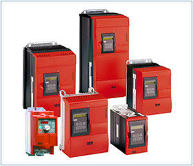
SEW inverter MCV40A series model
MCV40A0015-5A3-4-00
MCV40A0022-5A3-4-00
MCV40A0030-5A3-4-00
MCV40A0040-5A3-4-00
MCV40A0055-5A3-4-00
MCV40A0075-5A3-4-00
MCV40A0110-5A3-4-00
MCV40A0150-5A3-4-00
MCV40A0220-5A3-4-00
MCV40A0300-5A3-4-00
MCV40A0400-5A3-4-00
MCV40A0450-5A3-4-00
MCV40A0550-5A3-4-00
MCV40A0750-5A3-4-00
SEW inverter MDX61B series model
MDX61B0005-5A3-4-00
MDX61B0008-5A3-4-00
MDX61B0011-5A3-4-00
MDX61B0014-5A3-4-00
MDX61B0015-5A3-4-00
MDX61B0022-5A3-4-00
MDX61B0030-5A3-4-00
MDX61B0040-5A3-4-00
MDX61B0055-5A3-4-00
MDX61B0075-5A3-4-00
MDX61B0110-5A3-4-00
MDX61B0150-503-4-00
MDX61B0220-503-4-00
MDX61B0300-503-4-00
MDX61B0370-503-4-00
MDX61B0450-503-4-00
MDX61B0550-503-4-00
MDX61B0750-503-4-00
MDX61B0900-503-4-00
MDX61B1100-503-4-00
MDX61B1320-503-4-00
MDX61B0005-5A3-4-0T
MDX61B0008-5A3-4-0T
MDX61B0011-5A3-4-0T
MDX61B0014-5A3-4-0T
MDX61B0015-5A3-4-0T
MDX61B0022-5A3-4-0T
MDX61B0030-5A3-4-0T
MDX61B0040-5A3-4-0T
MDX61B0055-5A3-4-0T
MDX61B0075-5A3-4-0T
MDX61B0110-5A3-4-0T
MDX61B0150-503-4-0T
MDX61B0220-503-4-0T
MDX61B0300-503-4-0T
MDX61B0370-503-4-0T
MDX61B0450-503-4-0T
MDX61B0550-503-4-0T
MDX61B0750-503-4-0T
MDX61B0900-503-4-0T
MDX61B1100-503-4-0T
MDX61B1320-503-4-0T
SEW inverter MC07B series model
MC07B0003-2B1-4-00
MC07B0004-2B1-4-00
MC07B0005-2B1-4-00
MC07B0008-2B1-4-00
MC07B0011-2B1-4-00
MC07B0015-2B1-4-00
MC07B0022-2B1-4-00
MC07B0003-5A3-4-00
MC07B0004-5A3-4-00
MC07B0005-5A3-4-00
MC07B0008-5A3-4-00
MC07B0011-5A3-4-00
MC07B0015-5A3-4-00
MC07B0022-5A3-4-00
MC07B0030-5A3-4-00
MC07B0040-5A3-4-00
MC07B0055-5A3-4-00
MC07B0075-5A3-4-00
MC07B0110-5A3-4-00
MC07B0450-5A3-4-00
MC07B0550-5A3-4-00
MC07B0750-5A3-4-00
SEW inverter MDV60A series model
MDV60A0015-5A3-4-00
MDV60A0022-5A3-4-00
MDV60A0030-5A3-4-00
MDV60A0040-5A3-4-00
MDV60A0055-5A3-4-00
MDV60A0075-5A3-4-00
MDV60A0110-5A3-4-00
MDV60A0150-5A3-4-00
MDV60A0220-5A3-4-00
MDV60A0300-5A3-4-00
MDV60A0370-5A3-4-00
MDV60A0450-5A3-4-00
MDV60A0550-5A3-4-00
MDV60A0750-5A3-4-00
MDV60A0900-5A3-4-00
MDV60A1100-5A3-4-00
MDV60A1320-5A3-4-00
SEW inverter MCF40A series model
MCF40A0015-5A3-4-00
MCF40A0022-5A3-4-00
MCF40A0030-5A3-4-00
MCF40A0040-5A3-4-00
MCF40A0055-5A3-4-00
MCF40A0075-5A3-4-00
MCF40A0110-5A3-4-00
MCF40A0150-5A3-4-00
MCF40A0220-5A3-4-00
MCF40A0300-5A3-4-00
MCF40A0400-5A3-4-00
MCF40A0450-5A3-4-00
MCF40A0550-5A3-4-00
MCF40A0750-5A3-4-00
MCF41A0015-5A3-4-00
MCF41A0022-5A3-4-00
MCF41A0030-5A3-4-00
MCF41A0040-5A3-4-00
MCF41A0055-5A3-4-00
MCF41A0075-5A3-4-00
MCF41A0110-5A3-4-00
MCF41A0150-5A3-4-00
MCF41A0220-5A3-4-00
MCF41A0300-5A3-4-00
MCF41A0370-5A3-4-00
MCF41A0450-5A3-4-00
SEW inverter MCS41A series model
MCS41A0015-5A3-4-00
MCS41A0022-5A3-4-00
MCS41A0030-5A3-4-00
MCS41A0040-5A3-4-00
MCS41A0055-5A3-4-00
MCS41A0075-5A3-4-00
MCS41A0110-5A3-4-00
MCS41A0150-5A3-4-00
MCS41A0220-5A3-4-00
MCS41A0300-5A3-4-00
MCS41A0370-5A3-4-00
MCS41A0450-5A3-4-00
SEW inverter MCV41A series model
MCV41A0015-5A3-4-00
MCV41A0022-5A3-4-00
MCV41A0030-5A3-4-00
MCV41A0040-5A3-4-00
MCV41A0055-5A3-4-00
MCV41A0075-5A3-4-00
MCV41A0110-5A3-4-00
MCV41A0150-5A3-4-00
MCV41A0220-5A3-4-00
MCV41A0300-5A3-4-00
MCV41A0400-5A3-4-00
MCV41A0450-5A3-4-00
MCV41A0550-5A3-4-00
MCV41A0750-5A3-4-00
MC07B0003-2B1-4-00
MC07B0004-2B1-4-00
MC07B0005-2B1-4-00
MC07B0008-2B1-4-00
MC07B0011-2B1-4-00
MC07B0015-2B1-4-00
MC07B0022-2B1-4-00
MC07B0003-5A3-4-00
MC07B0004-5A3-4-00
MC07B0005-5A3-4-00
MC07B0008-5A3-4-00
MC07B0011-5A3-4-00
MC07B0015-5A3-4-00
MC07B0022-5A3-4-00
MC07B0030-5A3-4-00
MC07B0040-5A3-4-00
MC07B0055-5A3-4-00
MC07B0075-5A3-4-00
MC07B0110-5A3-4-00
MC07B0150-5A3-4-00
MC07B0220-5A3-4-00
MC07B0300-5A3-4-00
MC07B0370-5A3-4-00
MC07B0450-5A3-4-00
MC07B0550-5A3-4-00
MC07B0750-5A3-4-00
SEW inverter MCH41A series model
MCH41A0015-5A3-4-00
MCH41A0022-5A3-4-00
MCH41A0030-5A3-4-00
MCH41A0040-5A3-4-00
MCH41A0055-5A3-4-00
MCH41A0075-5A3-4-00
MCH41A0110-5A3-4-00
MCH41A0150-5A3-4-00
MCH41A0220-5A3-4-00
The common frequency setting modes of inverter mainly include: operator keyboard setting, contact signal setting, analog signal setting, pulse signal setting and communication mode setting. These frequency given modes have their own advantages and disadvantages, so they must be selected and set according to the actual needs. Meanwhile, different frequency given modes can be selected according to the functional needs for stacking and switching.
The control mode
The output voltage of low voltage general frequency conversion is 380 ~ 650V, the output power is 0.75 ~ 400kW, the working frequency is 0 ~ 400Hz, its main circuit adopts ac-dc - ac circuit. Its control mode has gone through the following four generations.
Sinusoidal pulse width modulation (SPWM) control mode
Its characteristic is the control circuit structure is simple, the cost is low, the mechanical characteristic hardness is also good, can satisfy the general transmission smooth speed regulation request, has been widely used in every field of the industry. However, at low frequency, due to the low output voltage, the torque is significantly affected by the voltage drop of stator resistance, which reduces the maximum output torque. In addition, its mechanical properties, after all, there is no direct current motor, and the static and dynamic torque capacity speed control performance is not satisfactory, and the system performance is not high, the control curve changes over load, torque response is slow, motor torque utilization rate is not high, low speed with the stator resistance and the existence of the inverter dead time effect and performance degradation, poor stability. Therefore, people developed vector control variable frequency speed regulation.
Voltage space vector (SVPWM) control mode
On the premise of the overall generation effect of three-phase waveform, it generates three-phase modulation waveform at one time and approximates the ideal circular rotating magnetic field track of the motor air gap for the purpose, and the inner cutting polygon approximates the circle. After being used in practice, it is improved, that is, frequency compensation is introduced to eliminate the error of speed control. The influence of stator resistance at low speed is eliminated by feedback estimation of flux linkage amplitude. The output voltage and current are closed loop to improve the dynamic accuracy and stability. However, there are many links in the control circuit and no torque regulation is introduced, so the performance of the system is not improved fundamentally.
Vector control (VC) mode
Vector control variable frequency speed regulation, it is the stator current of asynchronous motor in the three-phase system Ia, Ib, Ic, through the three phase - two phase transformation, equivalent to two phase static coordinates system, ac current Ia1Ib1 again by pressing the rotor field-oriented rotation transform, the equivalent into synchronous rotating coordinates of dc current Im1, It1 (Im1 is equivalent to the excitation current of dc motor; It1 is equivalent to the armature current which is proportional to the torque), and then the control quantity of dc motor is obtained by imitating the control method of dc motor. In essence, the ac motor is equivalent to dc motor, and the speed and magnetic field are controlled independently. Two components of torque and magnetic field are obtained by controlling rotor flux linkage and decomposing stator current. The vector control method is of epoch-making significance. However, in the practical application, the rotor flux linkage is difficult to be observed accurately, the system characteristics are greatly affected by the motor parameters, and the vector rotation transformation used in the control process of the equivalent dc motor is complex, so the actual control effect is difficult to achieve the ideal analysis result.
Direct torque control (DTC) mode
In 1985, DePenbrock, a professor at ruhr university in Germany, first proposed the DTC frequency conversion technology. To a great extent, this technology solves the shortage of vector control, and develops rapidly with novel control idea, simple system structure and excellent dynamic and static performance. The technology has been successfully applied to the high power ac transmission of electric locomotive traction. Direct torque control (DTC) directly analyzes the mathematical model of ac motor in the stator coordinate system and controls the magnetic linkage and torque of the motor. It does not need the ac motor to be equivalent to the dc motor, so it saves many complicated calculations in the vector rotation transformation. It does not need to imitate the control of dc motor, nor does it need to simplify the mathematical model of ac motor for decoupling.
Matrix intersection - intersection control
VVVF frequency conversion, vector control frequency conversion and direct torque control frequency conversion are all ac - dc - ac frequency conversion. Its common shortcomings are low input power factor, large harmonic current, large dc circuit needs a large energy storage capacitor, and the renewable energy can not be fed back to the grid, that is, can not carry out four-quadrant operation. For this reason, matrix ac - ac frequency conversion came into being. As a result of matrix ac-ac frequency conversion saves the middle dc link, thus saves the large volume, expensive electrolytic capacitor. It can achieve a power factor of l, sinusoidal input current and can run in four quadrants, the power density of the system is large. Although the technology is not mature, it still attracts many scholars to study it deeply. Its essence is not the indirect control current, magnetic linkage equivalent, but the torque is directly as the controlled quantity to achieve. The specific method is:
1. Control the stator flux linkage by introducing stator flux observer to realize the speed sensorless mode;
2. Automatic identification (ID) automatic identification of motor parameters based on accurate mathematical model of the motor;
3. Calculate the actual values corresponding to stator impedance, mutual inductance, magnetic saturation factor, inertia, etc. Calculate the actual torque, stator flux linkage and rotor speed for real-time control;
4. Realize the PWM signal generated by the band-band control by magnetic linkage and torque, and control the switching state of the inverter.
Need to control the motor and inverter itself
1) number of poles of the motor. General motor number is not more than (very appropriate, otherwise the inverter capacity will be appropriately increased.
2) torque characteristics, critical torque and accelerating torque. In the case of the same motor power, relative to the high overload torque mode, the inverter specification can be selected to.
3) electromagnetic compatibility. In order to reduce the interference of the main power supply, the reactor can be added in the intermediate circuit or the input circuit of the inverter, or the pre-isolation transformer can be installed. Generally, when the distance between the motor and the frequency converter is more than 50m, the reactor, filter or shield protection cable should be connected in the middle of them.
Matrix ac-ac frequency conversion has fast torque response (<2ms), high speed accuracy (±2%, no PG feedback), and high torque accuracy (<+3%). At the same time, it also has high starting torque and high torque precision, especially at low speed (including 0 speed), it can output 150% ~ 200% torque.
Choose the type of inverter, according to the type of production machinery, speed range, static speed accuracy, starting torque, decided to choose the most appropriate inverter control mode. The so-called suitable is both easy to use, but also economic, in order to meet the basic conditions and requirements of the process and production.


