ABB MOTOR QABP71M2A
ABB MOTOR QABP71M2B
ABB MOTOR QABP80M2A
ABB MOTOR QABP80M2B
ABB MOTOR QABP315L4A
ABB MOTOR QABP315L4B
ABB MOTOR QABP355M4A
ABB MOTOR QABP355L4A
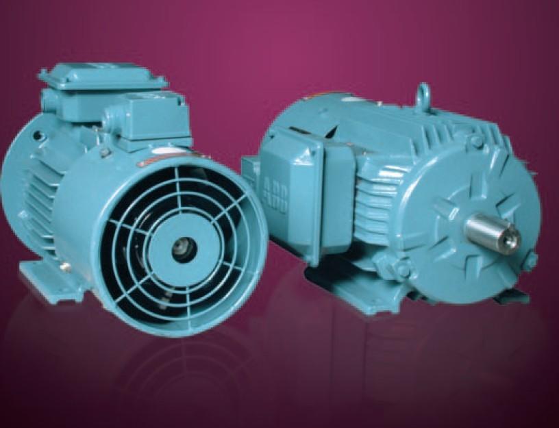
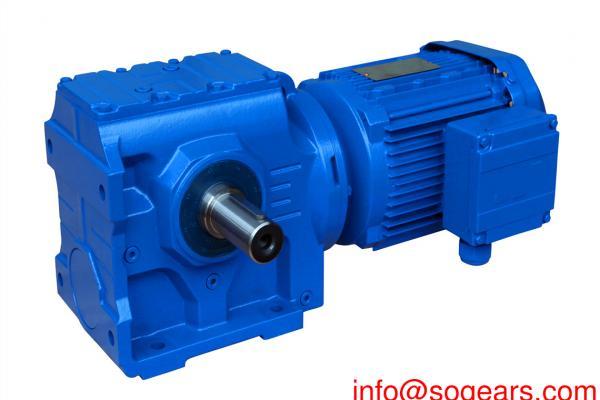
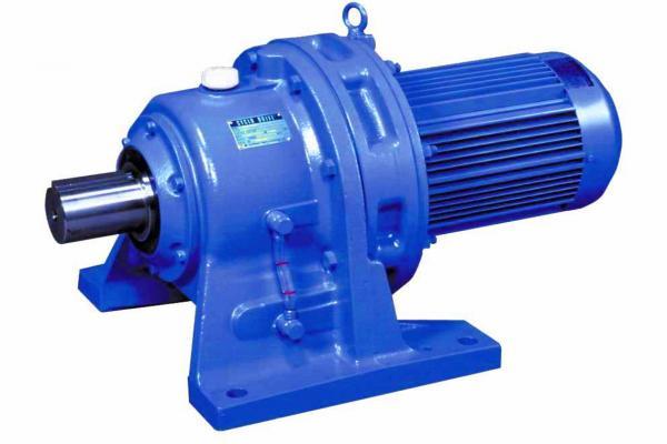
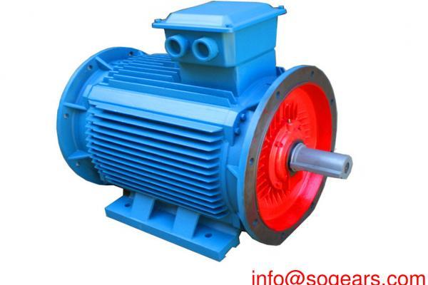
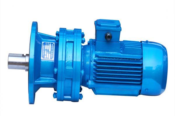
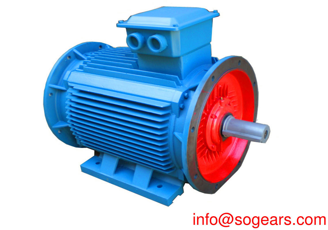
QABP series: The design of the variable frequency drive motor is reasonable, and it can be matched with similar frequency converters at home and abroad. It is highly interchangeable and versatile. Energy efficiency level is EFF2 / IE3
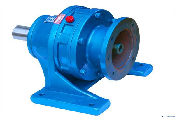
QABP series variable frequency speed regulating motor absorbs the advantages of products from advanced countries such as Germany and Japan, and applies computer-aided design technology for design. It can be matched with the same type of frequency conversion device at home and abroad, with strong interchangeability and versatility. The motor adopts a squirrel-cage structure, which is reliable in operation and easy to maintain. The motor is equipped with an axial fan separately to ensure that the motor has a good cooling effect at different speeds. The motor insulation adopts the F-class insulation structure widely used internationally, which improves the reliability of the motor. Corresponding indicators of motor power, foot mounting size and center height are completely consistent with QA series asynchronous motors. This series of motors can be widely used in industries such as light industry, textiles, chemical industry, metallurgy, machine tools, etc. that require speed-regulating rotating devices, and are an ideal power source for speed-regulating.
The power of this series of motors is from 0.25 kW to 200 kW, and the center height of the frame is from 71 mm to 315 mm.
Frequency conversion motor refers to a motor that runs continuously at 100% rated load in the range of 10% to 100% rated speed under standard environmental conditions, and the temperature rise will not exceed the motor's rated allowable value.
With the rapid development of power electronics technology and new semiconductor devices, AC speed regulation technology has been continuously improved and improved, and gradually improved inverters have been widely used in AC motors with their good output waveforms and excellent cost performance. For example: large-scale motors and medium and small roller motors used in steel mills, traction motors for railways and urban rail transit, elevator motors, crane motors for container lifting equipment, motors for pumps and fans, compressors, household appliances Motors have successively used AC variable frequency speed-regulating motors, and have achieved good results [1]. Adopting AC variable frequency speed regulating motor has significant advantages over DC speed regulating motor:
(1) Easy speed regulation and energy saving.
(2) The AC motor has a simple structure, small size, small inertia, low cost, easy maintenance, and durability.
(3) The capacity can be expanded to achieve high speed and high voltage operation.
(4) It can realize soft start and fast braking.
(5) No spark, explosion-proof, strong environmental adaptability. [1]
In recent years, international up-conversion speed-regulating transmissions have been developed at an annual growth rate of 13% to 16%, and have gradually replaced most DC speed-regulating transmissions. Because ordinary asynchronous motors operating with constant frequency and constant voltage power supply are used in variable frequency speed regulation systems, there are great limitations. Special inverter AC motors designed according to the application occasion and requirements have been developed abroad. For example, there are low-noise, low-vibration motors, motors with improved low-speed torque characteristics, high-speed motors, motors with tachogenerators, and vector-controlled motors [1].
Construction principle
When the slip rate of the asynchronous motor changes little, the speed is proportional to the frequency. It can be seen that changing the power frequency can change the speed of the asynchronous motor. In the frequency conversion speed regulation, it is always hoped that the main magnetic flux remains unchanged. If the main magnetic flux is greater than the magnetic flux during normal operation, the magnetic circuit is oversaturated to increase the excitation current and reduce the power factor. If the main magnetic flux is less than the magnetic flux during normal operation, the motor torque is reduced [1].
Development process edit
Current motor frequency conversion systems are mostly constant V / F control systems. The characteristics of this frequency conversion control system are simple structure and cheap manufacturing. This system is widely used in large places such as fans and where the dynamic performance requirements of the frequency conversion system are not very high. This system is a typical open-loop control system. This system can meet the smooth transmission requirements of most motors, but has limited dynamic and static adjustment performance, and cannot be used in applications with strict requirements on dynamic and static performance. local. In order to achieve the high performance of dynamic and static regulation, we can only use closed-loop control systems to achieve it. Therefore, some researchers have proposed a motor speed control method that controls the closed-loop slip frequency. This speed control method can achieve high performance in static dynamic speed control, but this system can only be obtained in motors with slower speeds. The application should be that when the speed of the motor is high, this system will not only achieve the purpose of saving power, but also cause the motor to generate a large transient current, which will cause the torque of the motor to change instantaneously. Therefore, in order to achieve higher dynamic and static performance at higher speeds, we must first solve the problem of transient current generated by the motor. Only by properly solving this problem can we better develop motor frequency conversion energy-saving control technology. [2]
Key FeaturesEdit
Special frequency conversion motor has the following characteristics:
Class B temperature rise design, class F insulation manufacturing. High polymer insulation material and vacuum pressure dip paint manufacturing process and special insulation structure are adopted to make the electrical windings with higher insulation withstand voltage and higher mechanical strength, which is sufficient for high-speed operation of the motor and resistance to high-frequency current shock and voltage of the inverter. Damage to insulation.
The balance quality is high, and the vibration level is R level (reduced vibration level). The mechanical parts have high machining accuracy, and the special high-precision bearings are used, which can run at high speed.
Forced ventilation cooling system, all use imported axial flow fan ultra-quiet, high life, strong wind. Ensure that the motor gets effective heat dissipation at any speed and can achieve high-speed or low-speed long-term operation.
Compared with traditional inverter motors, YP series motors designed by AMCAD software have a wider speed range and higher design quality. Special magnetic field design further suppresses high-harmonic magnetic fields to meet the requirements of wide frequency, energy saving and Low noise design index. With a wide range of constant torque and power speed regulation characteristics, the speed is stable and there is no torque ripple.
It has good parameter matching with various types of inverters, and with vector control, it can achieve zero speed full torque, low frequency large torque and high precision speed control, position control and fast dynamic response control. YP series frequency conversion special motors can be equipped with brakes and encoders to provide precise stopping, and achieve high-precision speed control through closed-loop speed control.
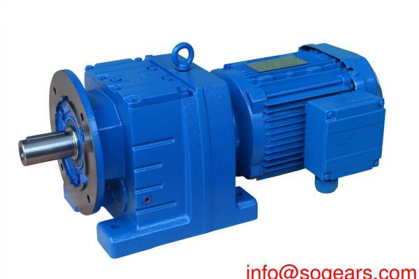
Adopting "reducer + frequency conversion dedicated motor + encoder + inverter" to achieve ultra-low speed stepless speed precise control. YP series inverter special purpose motors have good versatility, and their installation dimensions conform to IEC standards, and they are interchangeable with general standard motors.
Motor insulation damage edit
During the promotion and application of AC variable frequency motors, there have been a large number of early damages to the insulation of AC variable frequency motors. Many AC variable frequency motors have a service life of only 1 to 2 years, and some only have a few weeks. Even during the trial operation, the motor insulation is damaged, and it usually occurs between turns. This brings new problems to the motor insulation technology. Practice has proved that the theory of motor insulation design under power frequency sine wave voltage developed in the past few decades cannot be applied to AC variable frequency speed-regulated motors. It is necessary to study the damage mechanism of inverter motor insulation, establish the basic theory of AC inverter motor insulation design, and formulate industrial standards for AC inverter motors.
1 Damage to electromagnetic wires
1.1 Partial discharge and space charge
At present, variable-frequency speed-regulated AC motors are controlled by IGB T (Insulated Gate Diode) technology PWM (Pulse width m odulatio n-pulse width modulation) inverters. Its power range is about 0.75 to 500kW. IGBT technology can provide a current with a very short rise time. Its rise time is 20 ~ 100μs, and the generated electrical pulse has a very high switching frequency, reaching 20kHz. When a fast rising voltage from the inverter to the motor end, due to the impedance mismatch between the motor and the cable, a reflected voltage wave is generated. This reflected wave returns to the frequency converter, and then induces another reflected wave due to the impedance mismatch between the cable and the frequency converter, which is added to the original voltage wave, thereby generating a spike voltage at the leading edge of the voltage wave. The magnitude of the spike voltage depends on the rise time of the pulse voltage and the length of the cable [1].
Generally, when the length of the wire increases, an overvoltage occurs at both ends of the wire.The amplitude of the overvoltage at the motor end increases with the length of the cable and tends to be saturated. . The test shows that the overvoltage occurs at the rising and falling edges of the voltage, and the attenuation oscillation occurs. The attenuation obeys the exponential law, and the oscillation period increases with the length of the cable. There are two kinds of frequencies for the PWM driving pulse waveform. One is the switching frequency. The repetition frequency of the spike voltage is directly proportional to the switching frequency. The other is the basic frequency, which directly controls the speed of the motor. At the beginning of each basic frequency, the pulse polarity changes from positive to negative or from negative to positive. At this moment, the motor insulation is subjected to a full-scale voltage that is twice the peak voltage value. In addition, in a three-phase motor with embedded windings, the voltage polarity between adjacent two turns of different phases may be different, and the full-scale voltage jump may reach twice the peak voltage value. According to the test, the voltage waveform output by the PWM inverter in a 380 / 480V AC system has a measured peak voltage value of 1.2 to 1.5kV at the motor end, and in a 576 / 600V AC system, the measured voltage waveform The peak voltage value reaches 1.6 to 1.8 kV. It is very obvious that under this full-scale voltage, surface partial discharge occurs between the turns of the winding. Due to ionization, space charges will be generated in the air gap, and an induced electric field opposite to the applied electric field will be formed. When the voltage polarity changes, this reverse electric field is in the same direction as the applied electric field. In this way, a higher electric field is generated, which will lead to an increase in the number of partial discharges and eventually cause breakdown. Tests have shown that the magnitude of the electrical shock acting on these turn-to-turn insulation depends on the specific properties of the conductor and the rise time of the PWM drive current. If the rise time is less than 0.1 μs, 80% of the potential will be added to the first two turns of the winding, that is, the shorter the rise time, the greater the electrical shock, and the shorter the life of the inter-turn insulation [1].
1.2 Dielectric loss heating
When E exceeds the critical value of the insulator, its dielectric loss increases rapidly. When the frequency is increased, the partial discharge will increase accordingly, and as a result, heat will be generated, which will cause greater leakage current, which will cause Ni to rise faster, that is, the temperature rise of the motor will rise, and the insulation will age faster. In short, in the variable frequency motor, it is precisely due to the combined effects of the above-mentioned partial discharge, dielectric heating, space charge induction and other factors that cause the premature damage of the electromagnetic wire [1].
2 Damage to main insulation, phase insulation and insulation paint
As mentioned earlier, the use of a PWM variable frequency power supply increases the amplitude of the oscillating voltage at the terminals of the variable frequency motor. Therefore, the main insulation, phase insulation and insulating paint of the motor withstand higher electric field strength. According to tests, due to the combined effect of factors such as the voltage rise time, cable length, and switching frequency of the output terminal of the inverter, the peak voltage of the above terminal can exceed 3kV. In addition, when a partial discharge occurs between the turns of the motor windings, the electrical energy stored in the distributed capacitance in the insulation will become heat, radiation, mechanical and chemical energy, which will degrade the entire insulation system and reduce the breakdown voltage of the insulation, eventually leading to The insulation system was broken down [1].
3 Accelerated aging of insulation due to cyclic alternating stress
It adopts PWM frequency conversion power supply, so that the frequency conversion motor can start at very low frequency, low voltage and no inrush current, and can use various methods provided by the frequency converter to perform rapid braking. Because the variable frequency motor can achieve frequent starting and braking, the motor insulation is frequently under the effect of cyclic alternating stress, and the motor insulation is accelerated to age [1].
The problems of vibration caused by electromagnetic excitation force and mechanical transmission in ordinary asynchronous motors become more complicated in variable frequency motors. Various time harmonics contained in the variable frequency power supply interfere with the spatial harmonics inherent in the electromagnetic part to form various electromagnetic excitation forces. At the same time, because the motor has a wide operating frequency range and a large speed change, resonance occurs when it is consistent with the natural frequency of the mechanical part. Under the influence of electromagnetic excitation force and mechanical vibration, the motor insulation is subject to more frequent cyclic alternating stress, which accelerates the aging of the motor insulation.